Supporting plate nut riveting assisting device

A technology of auxiliary device and pallet nut, which is applied in the field of tool design, can solve problems such as small working surface, low production efficiency, and high labor intensity, and achieve the effects of reducing complexity and difficulty, reducing processing costs, and ensuring high quality

Active Publication Date: 2019-03-22
CHENGDU AIRCRAFT INDUSTRY GROUP
View PDF15 Cites 4 Cited by
  • Summary
  • Abstract
  • Description
  • Claims
  • Application Information

AI Technical Summary

Problems solved by technology

[0002] During the assembly process of small aircraft, the assembly of connectors involving a large number of detachable covers, protective covers and other parts is involved, especially there are a large number of bracket nuts on profiles and strip plates And the riveting part of the rivet is in the closed angle area with narrow space (that is, the angle formed by the profile, strip plate and other parts and the main body part of the fuselage is less than 90°), the portable riveting machine used cannot be used in a large area due to the limitation of the working part, so , t...

Method used


Image

  • Supporting plate nut riveting assisting device
  • Supporting plate nut riveting assisting device
  • Supporting plate nut riveting assisting device

Examples


Embodiment 1

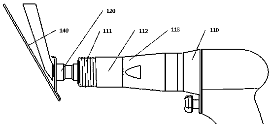
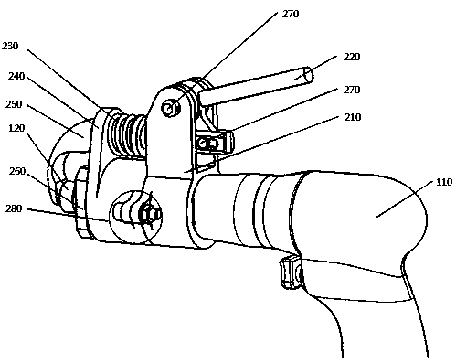
[0042] An auxiliary device for riveting a pallet nut, such as Figure 1-Figure 5 As shown, it includes a front frame 240, a rear frame 210, an elastic handle 220, an elbow top iron 250, and a lock nut 260. The front frame 240 includes a main body 241 and a large ear 242 vertically arranged on the main body 241. The rear frame 210 includes a cylinder 211 and a mounting seat 212 vertically arranged on the outside of the cylinder 211; Pass through the cylinder 211, the main body 241 in turn and connect with the lock nut 260; the mounting seat 212 includes upper convex plates arranged parallel to each other and a mounting plate arranged between adjacent upper convex plates, the mounting plate and The big ears 242 are arranged in parallel, and the big ears 242 and the mounting plate are respectively provided with a cavity 212c and a mounting plate 212b; one end of the elastic handle 220 is hingedly arranged on the top between adjacent upper convex plates, and is elastically One en...

Embodiment 2

[0045] This embodiment is further optimized on the basis of embodiment 1, as Figure 8 , Figure 9 As shown, the driving end of the elbow top iron 250 is provided with a through rectangular groove 252a, and the outer sides of the rectangular groove 252a are respectively provided with a plane, and the plane is provided with a through elliptical hole along the axis; The lug 223 is correspondingly provided with an elliptical hole, and the axis of the elliptical hole on the lug 223 coincides with the axis of the hinge hole of the elastic handle 220; the lug 223 is slidably connected in the rectangular groove 252a, so The lug 223 is connected to the rectangular groove 252a through a pin 270, and the pin 270 is slidably connected along the axis in the elliptical hole; the elbow top iron 250 includes an angled column 253, a first cylinder 253a, and a second cylinder connected in sequence. Two cylinders 252; the diameter of the first cylinder 253a is greater than the diameter of the ...

Embodiment 3

[0049] This embodiment is further optimized on the basis of embodiment 2, as Figure 7 As shown, the elastic handle 220 includes an annular cylinder 221, a cylinder handle 222, and a lug 223; the annular cylinder 221 is provided with a hinge hole along the axis, and the annular cylinder 221 is hingedly arranged The top between adjacent upper convex plates; the outer wall of the annular cylinder 221 is respectively connected with a lug 223 and a cylinder handle 222; An escape port 253c and a working plane 253b are arranged in sequence from top to bottom.

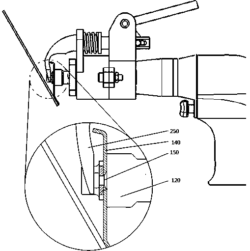
[0050] In the present invention, through the setting of the hinged hole, the pin hole on the mounting seat 212 of the annular column 221 and the rear frame 210 is hinged through the pin 270, so that the elastic handle 220 has a fulcrum when driving the elbow push iron 250, ensuring that the elbow pushes The drive of the iron 250; through the parallel setting of the working surface of the rivet card 120 and the working plane ...


PUM


Abstract

The invention discloses a supporting plate nut riveting assisting device. The supporting plate nut riveting assisting device comprises a front machine frame, a rear machine frame, a tight-and-loose handle, elbow ejector iron and a locking nut. The front machine frame comprises a main body and a large lug, the rear machine frame comprises a cylinder body and a mounting seat; the working end of a riveter sequentially penetrates through the cylinder body and the main body and is connected to the locking nut; a mounting plate is disposed in parallel with the large lug, and the large lug and the mounting plate are separately provided with a cavity and a mounting plate correspondingly; and one end of the tight-and-loose handle is installed at the top of the mounting plate in a hinged mode; the elbow ejector iron includes an assisting end and a driving end, wherein the assisting end is connected with the driving end through a bend cylinder body; and the driving end of the elbow ejector iron sequentially penetrates through a mounting hole, the mounting plate and is connected with a convex lug in a sliding mode. The supporting plate nut riveting assisting device reduces the complexity and difficulty of the riveting of a workpiece to be machined, improves the stability of the rapid forming and riveting quality of rivets, greatly reduces the difficulty and complexity of the riveting, andmeets the riveting demands of high quality and high efficiency in a space limited area.

Description

technical field [0001] The invention belongs to the technical field of tool design, and in particular relates to an auxiliary device for riveting a pallet nut. Background technique [0002] During the assembly process of small aircraft, the assembly of connecting parts involving a large number of detachable covers, protective covers, etc., especially in the closed corner area with a small space (that is, the profile The angle formed by parts such as belt plates and the main body parts of the fuselage is less than 90°), and the portable riveting machine used cannot be used in a large area due to the limitation of the working position. Therefore, the current method for riveting in the narrow closed angle area is: two One person cooperates with the pneumatic rivet gun and the top iron for riveting, one person operates the rivet gun to rivet, and the other uses the special top iron to top the rivets, because the special top iron is limited by space, its working surface is small,...

Claims


Application Information

Patent Timeline
IPC IPC(8): B21J15/14B21J15/30
CPCB21J15/142B21J15/30
Inventor 张三
Owner CHENGDU AIRCRAFT INDUSTRY GROUP
Why Eureka
Try Eureka