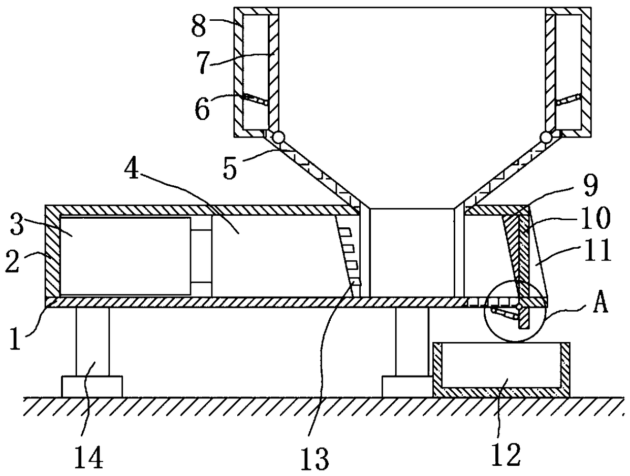
Pop can compression and collection device for environmental-protection construction

A technology for collecting devices and pop-top cans, which is applied to presses, manufacturing tools, etc., can solve the problems of large space occupation, more space occupied, and less pop-top cans, and achieve the effects of convenient feeding, improved efficiency, and convenient feeding

Active Publication Date: 2019-03-22
来安县宝成建筑工程有限公司
View PDF8 Cites 7 Cited by
  • Summary
  • Abstract
  • Description
  • Claims
  • Application Information

AI Technical Summary

Problems solved by technology

[0002] In daily life, there are not only a large number of discarded cans but also a large space, which causes great troubles to recycling, especially stacking and transportation, and wastes a lot of human and material resources
[0003] The existing can compression collection device generally uses a hydraulic rod to drive the pressure plate to compress the can into a can cake. When this compression collection device is in use, due to the large uncompressed volume of the can, it occupies more space, resulting in a compression stroke. The amount of compressible cans is small, which in turn leads to low compression and collection efficiency of cans, and when the cans are compressed, under the action of pressure, the can cakes are easy to adhere to the wall of the pressure plate, which makes it difficult to unload when the cans are compressed and collected

Method used


Image

  • Pop can compression and collection device for environmental-protection construction
  • Pop can compression and collection device for environmental-protection construction
  • Pop can compression and collection device for environmental-protection construction

Examples


Embodiment Construction

[0021] The following will clearly and completely describe the technical solutions in the embodiments of the present invention with reference to the accompanying drawings in the embodiments of the present invention. Obviously, the described embodiments are only some, not all, embodiments of the present invention.

[0022] In describing the present invention, it should be understood that the terms "upper", "lower", "front", "rear", "left", "right", "top", "bottom", "inner", " The orientation or positional relationship indicated by "outside", etc. is based on the orientation or positional relationship shown in the drawings, and is only for the convenience of describing the present invention and simplifying the description, rather than indicating or implying that the referred device or element must have a specific orientation, so as to Specific orientation configurations and operations, therefore, are not to be construed as limitations on the invention.

[0023] refer to Figure ...


PUM


Abstract

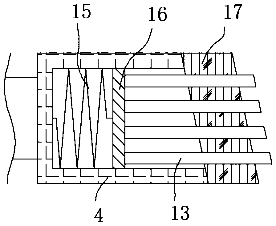
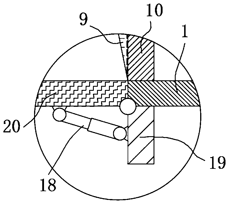
The invention discloses a pop can compression and collection device for environmental-protection construction. The device comprises a base plate; a compression shell is arranged on the outer wall of the top of the base plate; an unloading port is formed in the outer wall of the top of the compression shell; a lower can plate is arranged on the inner wall of the unloading port; a hopper is arrangedon the outer wall of the top of the lower can plate; second hydraulic rods are arranged on the inner walls of the opposite sides of the hopper; pressing plates are arranged on the outer walls of onesides of the second hydraulic rods; the outer walls of the bottoms of the pressing plates are arranged on the outer wall of the top of the lower can plate; the inner wall of one side of the compression shell is connected with a first hydraulic rod through screws; a pressing shell is arranged on the outer wall of one side of the first hydraulic rod; a spring is arranged on the inner wall of one side of the pressing shell; and a pushing plate is arranged on the outer wall of one side of the spring. The device can compress more pop cans through once compression travel to improve the pop can compression efficiency, and can prevent pop can cakes from attaching on a compression shell to cause incapability of unloading, so that the unloading is more convenient.

Description

technical field [0001] The invention relates to the technical field of environmental protection construction, in particular to a compression collection device for pop cans used in environmental protection construction. Background technique [0002] In daily life, discarded pop cans not only have a large number but also occupy a large space, which has caused great troubles to recycling, especially stacking and transportation, and wasted a lot of human and material resources. [0003] The existing can compression collection device generally uses a hydraulic rod to drive the pressure plate to compress the can into a can cake. When this compression collection device is in use, due to the large uncompressed volume of the can, it occupies more space, resulting in a compression stroke. The amount of compressible cans is small, which in turn leads to low compression and collection efficiency of the cans, and when the cans are compressed, under the action of pressure, the can cakes t...

Claims


Application Information

Patent Timeline
IPC IPC(8): B30B9/32B30B15/30B30B15/32
CPCB30B9/321B30B15/30B30B15/32
Inventor 文露钱坤郭晓晓罗辉
Owner 来安县宝成建筑工程有限公司
Why Eureka
Try Eureka