Compound material electrical insulating box and production method thereof

A composite material and electrical insulation technology, which is applied in the direction of electrical components, electrical equipment casings/cabinets/drawers, casings/cabinets/drawer components, etc., can solve the difficulty of maintaining electrical equipment, cost and effort, and electrical systems Bulkiness and other problems, to achieve the effect of being suitable for mass production, good mechanical properties, and good insulation properties

Active Publication Date: 2019-03-22
ZHUZHOU TIMES NEW MATERIALS TECH
View PDF6 Cites 7 Cited by
  • Summary
  • Abstract
  • Description
  • Claims
  • Application Information

AI Technical Summary

Problems solved by technology

Most of the electrical boxes in the past are made of metal materials. Although they can resist the impact of the outside world, they are easy to corrode and have no insulation function. The insulation between electrical equipment and the outside world needs to be realized by filling the electrical box with insulating substances such as transformer oil and silica gel. , which not only makes the entire electrical system cumbersome, but also has problems such as high insulation costs and difficult maintenance of electrical equipment
With the rapid development of rail transit and the continuous increase in the speed of rail vehicles, higher requirements have been placed on the lightweight and safety performance of rail transit electrical equipment. In the past, most electrical boxes were made of metal materials, which were prone to corrosion, poor insulation, and heavy weight. problems such as large size and difficult maintenance, especially in insulation and maintenance, it takes more cost and effort

Method used


Image

  • Compound material electrical insulating box and production method thereof
  • Compound material electrical insulating box and production method thereof
  • Compound material electrical insulating box and production method thereof

Examples


Embodiment Construction

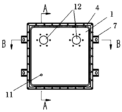
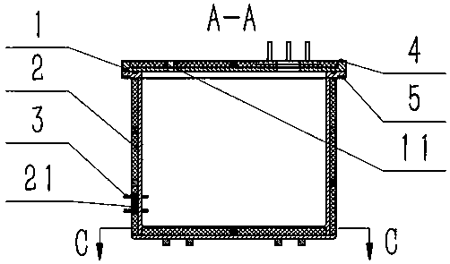
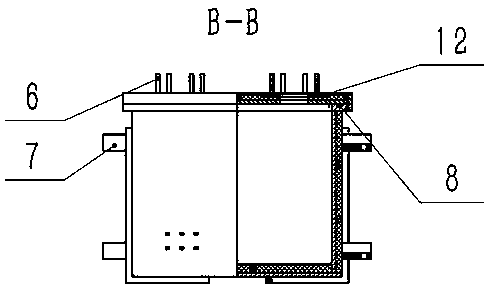
[0035] Please refer to figure 1 , figure 2 , image 3 and Figure 4 , a composite material electrical insulation box, including box cover 1, box body 2, input and output terminals 3, upper flange 4, lower flange 5, guide post 6, box external mounting parts 7, sealing strip 8. The box body is a cuboid structure, the upper part of the box body has flange edges extending outward, and the inside of the box body is a cuboid cavity. Closed sealing grooves distributed around the opening of the upper end of the box body are provided on the edge of the flange near the inner wall, and the sealing strip 8 is located in the sealing grooves. A bolt hole 1 is provided on the periphery of the sealing groove on the casing, and the lower flange 5 is positioned at the bottom of the flange side of the casing 2, and the lower flange is provided with a bolt hole 2 that cooperates with the bolt hole 1 on the casing 2.

[0036] The front side wall (front side) of the box is provided with a cubo...


PUM

PropertyMeasurementUnit
thicknessaaaaaaaaaa
thicknessaaaaaaaaaa
thicknessaaaaaaaaaa

Abstract

The invention discloses a compound material electrical insulating box and a production method thereof. The compound material electrical insulating box comprises a box body, a box cover connected withthe upper surface of the box body, and an input and output binding post installed on the lower portion of the front side surface of the box body, and further comprises box body external portion installation parts used for box body installation; the box body external portion installation parts are connected with both the left side surface and the right side surface of the box body; both the box body and the box cover are of sandwich structures, and the sandwich structures comprise surface layers made from a compound material, and sandwiches which are made from reinforcing ribs and foam. The boxbody is produced at first; then the box cover is produced, then a lower flange is bonded with the box body, and an upper flange is bonded with the box cover; finally, the box cover and the box body are connected fixedly in a sealed mode by bolts. The compound material electrical insulating box has the advantages of being high in strength, light in weight and good in insulating performance, and issuitable for being popularized and applied onto electrical equipment of railway vehicles. The electrical box produced by adopting the method has very good mechanical performance, corrosion resistanceperformance and insulating performance and a good lightweight effect.

Description

technical field [0001] The invention relates to the technical field of rail transit electrical equipment. Background technique [0002] The electrical system is the key center of the rail vehicle, and it is very important to ensure its safety and reliability. As a safety protection device for electrical equipment, the electrical box's structural design is very critical. In addition to resisting external vibration and shock, general electrical equipment also needs to ensure its insulation from the outside world. Most of the electrical boxes in the past are made of metal materials. Although they can resist the impact of the outside world, they are easy to corrode and have no insulation function. The insulation between electrical equipment and the outside world needs to be realized by filling the electrical box with insulating substances such as transformer oil and silica gel. , which not only makes the entire electrical system cumbersome, but also has problems such as high in...

Claims


Application Information

Patent Timeline
Patent Type & Authority Applications(China)
IPC IPC(8): B61C17/00H05K5/02B29C70/70
CPCB29C70/70B61C17/00H05K5/0217
Inventor 张元刘波李建林严立专樊凯王遵周升
Owner ZHUZHOU TIMES NEW MATERIALS TECH
Why Eureka
Try Eureka