
Vertical-horizontal connecting node for connecting module frames

A technology for horizontal connection and connection of modules, applied in the direction of architecture, building structure, etc., can solve the problems of no connection between modules and frames, affecting the application scope of modular buildings, and high integration of modular houses, so as to achieve occupancy. Small space, improved assembly speed, and the effect of ensuring installation quality

Inactive Publication Date: 2019-03-22
SHANGHAI BAOYE GRP CORP
View PDF5 Cites 0 Cited by
  • Summary
  • Abstract
  • Description
  • Claims
  • Application Information

AI Technical Summary

Problems solved by technology

[0002] Due to the high integration of modular houses, it is generally not allowed to damage the decoration of the house, which limits the application of conventional steel structure nodes in modular houses. The "Technical Regulations for Container Modular Houses" only gives the vertical connection form There are two types of joints, corner joints and pad joints, but these two forms only meet the requirements of hinge joints. Therefore, when modular buildings are applied to higher-rise buildings, they need to connect frames, but the existing regulations do not provide the connection between modules and frames. node form
This affects the scope of application of modular buildings to a certain extent

Method used


Image

  • Vertical-horizontal connecting node for connecting module frames
  • Vertical-horizontal connecting node for connecting module frames
  • Vertical-horizontal connecting node for connecting module frames

Examples


Embodiment Construction

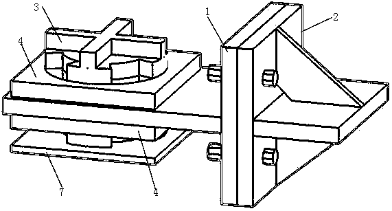
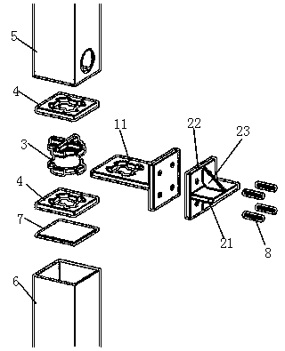
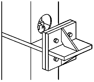
[0028] Such as Figure 1-4 Shown: a vertical and horizontal connection node for connecting module frames, which includes upper and lower column connecting plates 1, frame connecting plates 2, rotating parts 3, column end connecting plates 4, upper column connecting pieces 5, and lower column connecting pieces 6. Horizontal plate 7 and high-strength bolt 8;

[0029] The upper and lower column connecting plates are connected to the frame connecting plate. The upper and lower surfaces of the upper and lower column connecting plates are respectively provided with column end connecting plates. The rotating parts are arranged in the column end connecting plates and the upper and lower column connecting plates. The end connecting plate extends inside, the lower end of the rotating part is provided with a horizontal plate, the upper column connecting piece and the lower column connecting piece are respectively arranged on the upper and lower surfaces of the upper and lower column connect...


PUM


Abstract

The invention relates to a vertical-horizontal connecting node for connecting module frames. The vertical-horizontal connecting node comprises an upper-lower column connecting plate, a frame connecting plate, rotary parts, column-end connecting plates, an upper column connecting piece, a lower column connecting piece, horizontal plates and high-strength bolts. The upper-lower column connecting plate and the frame connecting plate are connected, the upper surface and the lower surface of the upper-lower column connecting plate are respectively provided with the column-end connecting plates, therotary parts are arranged in the column-end connecting plates and the upper-lower column connecting plate, the upper ends and the lower ends of the rotary parts extend out of the column-end connecting plates, the lower ends of the rotary parts are provided with the horizontal plates, the upper column connecting piece and the lower column connecting piece are respectively arranged on the upper surface and the lower surface of the upper-lower column connecting plate and sleeve the rotary parts and the column-end connecting plates, and one side of the upper column connecting piece is provided with an installing hole. The vertical-horizontal connecting node completely meets the requirement that an integrated modular building is decorated without damage, site welding is avoided, and the installing efficiency is improved.

Description

Technical field [0001] The invention relates to the technical field of building steel structure connection, in particular to vertical and horizontal connection nodes for connecting module frames. Background technique [0002] Due to the high integration of modular houses, it is generally not allowed to damage the decoration of houses, which limits the application of conventional steel structure nodes in modular houses. The "Technical Regulations for Container Modular Houses" only gives the vertical connection form Corner piece connection node and cushion piece connection are two types of nodes, but these two types only meet the requirements of articulation. Therefore, when modular buildings are used in higher-rise buildings, they need to be connected to the frame, but the existing regulations do not give the module and frame connection The node form. This has affected the application range of modular buildings to a certain extent. Summary of the invention [0003] The present in...

Claims


Application Information

Patent Timeline
Patent Type & Authority Applications(China)
IPC IPC(8): E04B1/24E04B1/58
CPCE04B1/2403E04B2001/2406E04B2001/2415E04B2001/2418
Inventor 隋炳强罗兴隆潘斯勇赵奋邹温源
Owner SHANGHAI BAOYE GRP CORP
Learn More