
Circuit board detection device

A detection device and circuit board technology, applied in the direction of measuring device, measuring device casing, electronic circuit testing, etc., can solve the problem of not being able to place two kinds of circuit boards at the same time, so as to reduce production cost, improve the effect of degaussing, and improve adaptability Effect

Inactive Publication Date: 2019-03-22
鹤山市泰利诺电子有限公司
View PDF0 Cites 2 Cited by
  • Summary
  • Abstract
  • Description
  • Claims
  • Application Information

AI Technical Summary

Problems solved by technology

[0003] In the circuit board production line, the main production is the control board and power board of the vacuum cleaner, that is, the circuit board includes the control board and the power board. In the detection process of the circuit board, the existing detection equipment can only detect the power board alone. Or the control board, mainly because the outlines of the control board and the power board are different, the placement slot on a testing device can only match the control board or the power board, and cannot place two kinds of circuit boards at the same time, so when testing, The power board and the control board need to be tested by separate equipment. When in use, different testing equipment needs to be replaced every time a different product is produced.

Method used


Image

  • Circuit board detection device
  • Circuit board detection device
  • Circuit board detection device

Examples


Embodiment Construction

[0017] Embodiments of the present invention are described in detail below, examples of which are shown in the drawings, wherein the same or similar reference numerals designate the same or similar elements or elements having the same or similar functions throughout. The embodiments described below by referring to the figures are exemplary and are intended to explain the present invention and should not be construed as limiting the present invention.

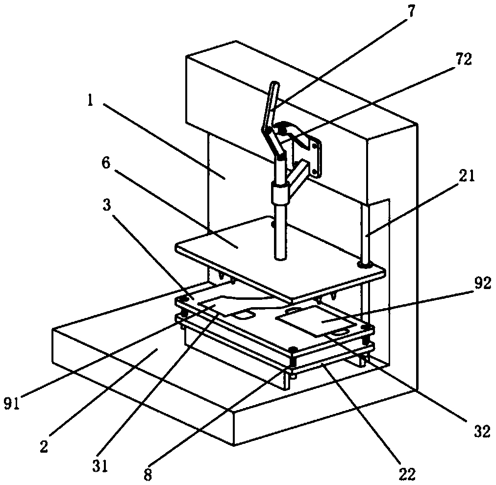
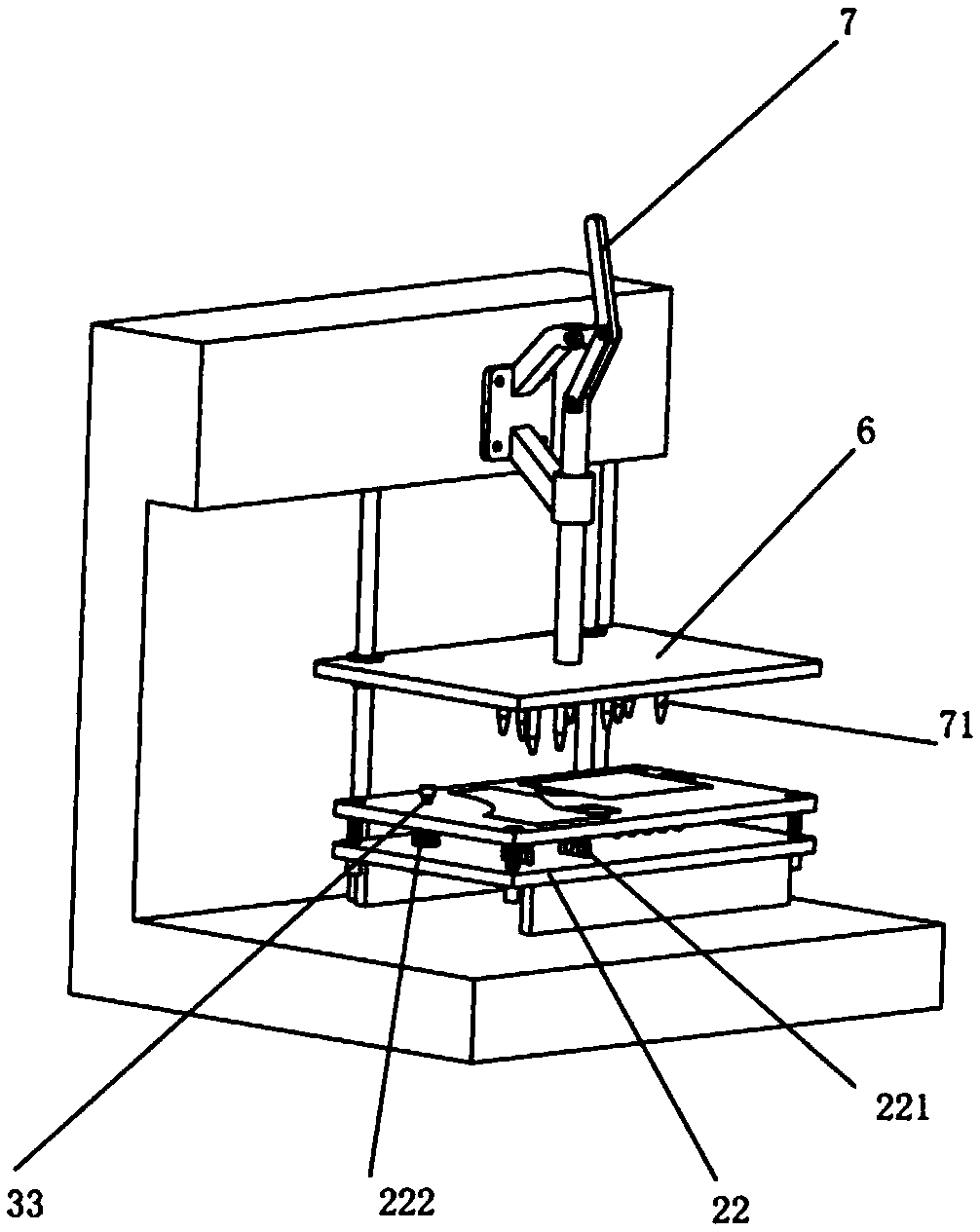
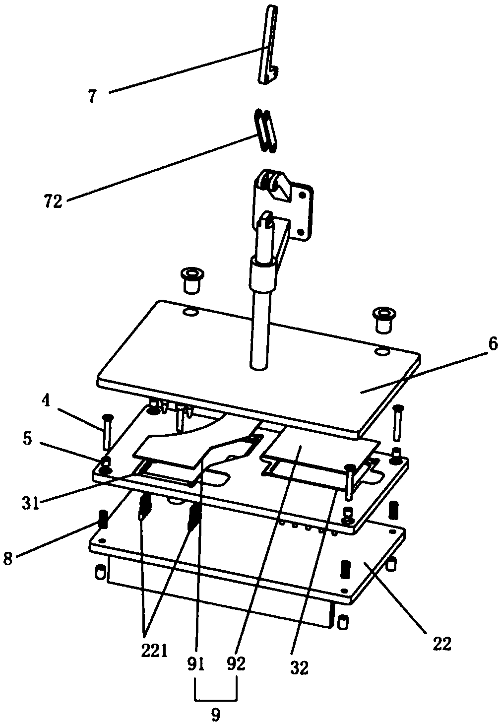
[0018] refer to Figure 1 to Figure 3 , a circuit board detection device, comprising a frame 1, the frame 1 is provided with a workbench 2, the workbench 2 is provided with a base 22, the base 22 is provided with a detection sensor 221 for detecting a circuit board 9, and is mounted on the machine The frame 1 is provided with a detection circuit for detecting the circuit board 9, and the detection sensor 221 is connected to the detection circuit to detect the circuit board 9. On the base 22, a placement plate 3 for placing the ci...


PUM


Abstract

The invention discloses a circuit board detection device. The technical scheme mainly includes that the circuit board detection device comprises a framework; a worktable is arranged on the framework,a bottom plate is arranged on the worktable, and probes for detecting a circuit board are arranged on the bottom plate. The circuit board detection device is characterized in that an arranging plate for placing the circuit board is slidably connected onto the bottom plate, a pressure plate for pushing the circuit board is arranged on the framework and is positioned above the arranging plate, firstarranging grooves and second arranging grooves are formed in the arranging plate, the first arranging grooves are matched with the outer contour of a power panel, and the second arranging grooves arematched with a control panel. The circuit board detection device has the advantages that the first arranging grooves and the second arranging grooves are formed in the arranging plate, the power panel and the control panel can be placed on the arranging plate at the moment, accordingly, corresponding functions can be detected, the power panel and the control panel can be detected by the single circuit board detection device at the moment, and the adaptability of the circuit board detection device can be improved; equipment on production lines does not need to be frequently replaced, accordingly, the work efficiency can be improved, and the production cost can be reduced.

Description

technical field [0001] The invention relates to the field of circuit board production auxiliary equipment, in particular to a circuit board detection device. Background technique [0002] At present, in the production of power boards and control boards of vacuum cleaners, in order to improve production efficiency, most of them adopt assembly line production. The production process is roughly as follows. First, batch welding is performed, and electrical components that can withstand high temperatures are inserted into the circuit boards. Then the conveyor belt will The circuit boards are sent into the tin furnace for batch welding. After the circuit boards are output from the tin furnace, they are transported by the conveyor belt for welding of individual electrical components. The welding objects are mainly electrical components that are not resistant to high temperatures. After welding, The finished power board or control board is placed on the conveyor belt, and the convey...

Claims


Application Information

Patent Timeline
Patent Type & Authority Applications(China)
IPC IPC(8): G01R31/28G01R1/04
CPCG01R31/28G01R1/0408
Inventor 詹贵全
Owner 鹤山市泰利诺电子有限公司
Learn More