
Microswitch bracket and overflow protection device applied in same

A micro switch and body technology, applied in the direction of electric switches, electrical components, circuits, etc., can solve the problems of electric shock hazard, troublesome assembly, troublesome operation, etc., and achieve the effect of sensitive action, convenient installation and disassembly, and tight coordination.

Pending Publication Date: 2019-03-22
NINGBO MEIGAO KITCHENWARE CO LTD
View PDF0 Cites 0 Cited by
  • Summary
  • Abstract
  • Description
  • Claims
  • Application Information

AI Technical Summary

Problems solved by technology

The setting of the bottom shell greatly improves the aesthetics and safety of the product. However, if water leaks when the overflow is insufficient or the overflow device fails, the leaked water will collect inside the bottom shell. If the collected water is not removed in time or the water inlet valve is not cut off in time, it may cause the electric control unit in the bottom shell to fail or cause electric shock
[0003] The bottom of the tank type fruit and vegetable cleaning machine in the prior art is provided with an overflow protection device, the overflow protection device is to fix the micro switch on the inner bottom wall of the bottom shell, and then use the buoyancy of the float to touch The contact of the micro switch, and then the micro switch cuts off the water inlet unit to stop the water intake; the micro switch of the overflow protection device is installed on the bracket, but there is also a base for the float to be installed under the bracket, The base and the bracket are detachable, but when assembling, the base must be fixed on the inner bottom wall of the bottom case first, then the float is placed on the base, and finally the bracket is assembled, which is cumbersome and difficult to assemble. It is cumbersome to calibrate the position of the micro switch on the float and the bracket

Method used


Image

  • Microswitch bracket and overflow protection device applied in same
  • Microswitch bracket and overflow protection device applied in same
  • Microswitch bracket and overflow protection device applied in same

Examples


Embodiment Construction

[0024] The present invention will be described in further detail below in conjunction with the accompanying drawings and specific embodiments.

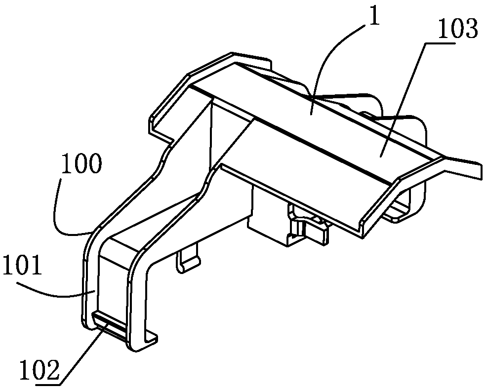
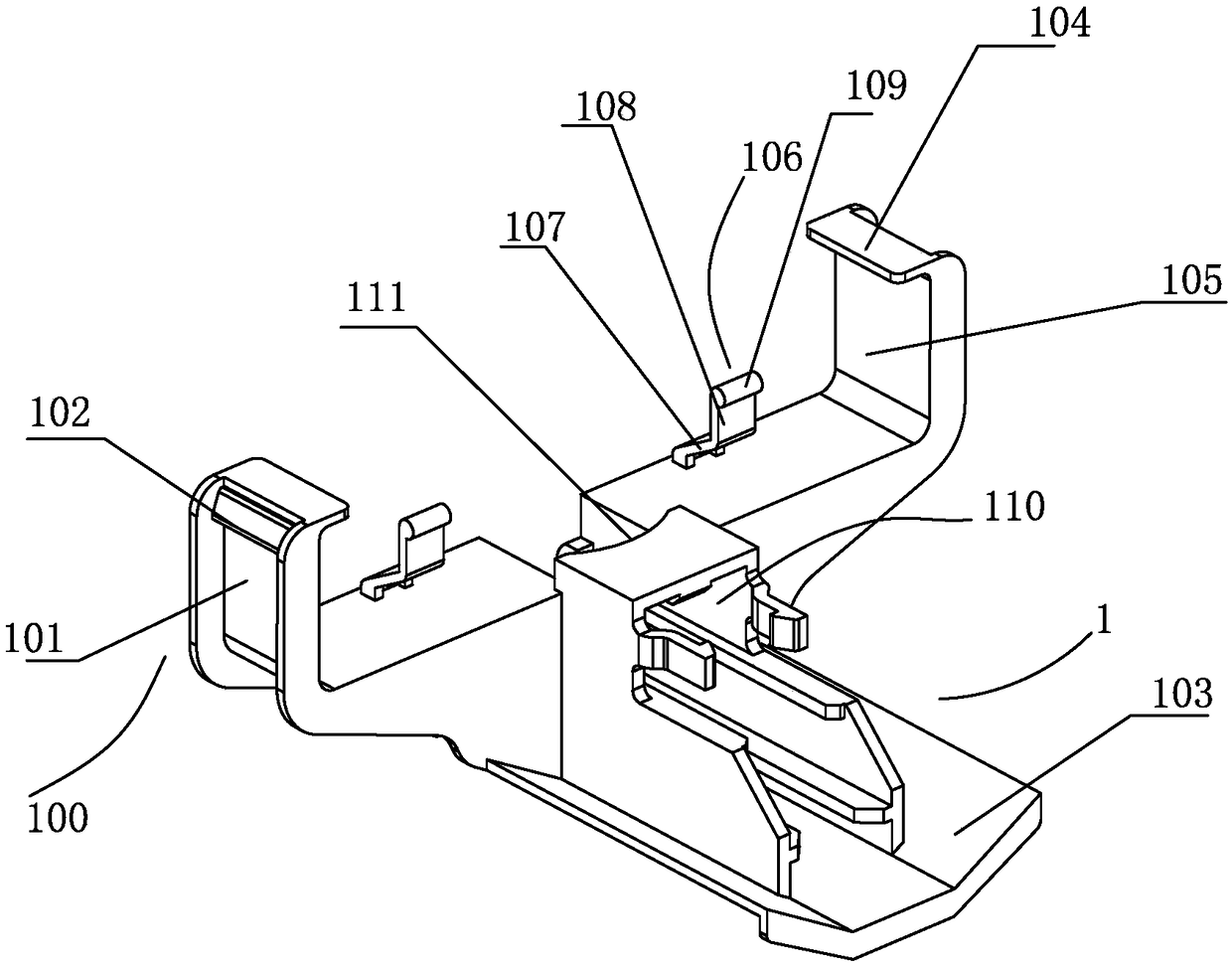
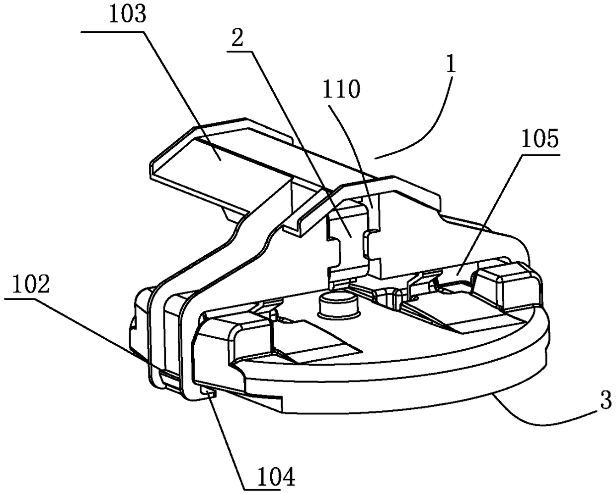
[0025] Such as figure 1 and figure 2 shown;

[0026] The present invention is a micro switch bracket, which includes a bracket body 1, the bracket body 1 is provided with a connecting part for the micro switch 2 to connect to, and both ends of the bracket body 1 are extended downwards with connecting parts. The arms 100, the lower ends of the two connecting arms 100 are provided with limiting pieces 104 inwardly, and an accommodation space 105 for installing the float assembly 3 is formed between the limiting pieces 104 and the bottom of the bracket body 1, and the float assembly 3 is in the There is a gap for moving up and down in the accommodation space 105 . The bracket body of the micro switch bracket not only has a connecting portion for the micro switch to connect to, but also utilizes connecting arms extending downward at b...


PUM


Abstract

The invention discloses a microswitch bracket and an overflow protection device applied in same. The microswitch bracket comprises a bracket body, wherein the bracket body is provided with a connecting portion for connecting a microswitch. Two ends of the bracket body extend downward and are provided with connecting arms. The lower ends of the two connecting arms are respectively provided with a limiting piece inwardly, and the limiting piece and the bottom of the bracket body form a receiving space for a float assembly to be installed, and the float assembly has space to move up and down in the receiving space. The microswitch bracket and the overflow protection device applied in same can install the microswitch, and also can install the float assembly, so that the position of the float assembly and the microswitch are relatively fixed.

Description

technical field [0001] The invention relates to the technical field of kitchen appliances, in particular to a micro switch bracket and an overflow protection device applied thereto. Background technique [0002] The sink type fruit and vegetable cleaning machine integrates the function of automatically cleaning fruits and vegetables on the sink. It has the function of automatically cleaning fruits and vegetables. Its structure generally includes a tank installed on the kitchen countertop. The top of the tank has an opening, and there is a washing cavity, the bottom of which is connected through a drain pipe; the tank body generally includes a cleaning tank and a fruit and vegetable cleaning tank, and the fruit and vegetable cleaning tank is provided with a spray device for spraying and washing the fruits and vegetables, and the bottom of the fruit and vegetable cleaning tank is provided with Ultrasonic generators are used to emit ultrasonic waves into the water and use ultra...

Claims


Application Information

Patent Timeline
IPC IPC(8): H01H35/18
CPCH01H35/18
Inventor 梅海滨
Owner NINGBO MEIGAO KITCHENWARE CO LTD
Learn More