
Guider for flaky object conveying

A technology of guides and sheets, applied in the direction of instruments, object supply, and sending objects, etc., can solve the problems of multi-transmission parts, complicated operation, complex guide structure, etc., and achieve reasonable and simple structure design, simple control, and connection relationship involves reasonably simple effects

Active Publication Date: 2016-11-09
广州智清电子科技有限公司
View PDF8 Cites 5 Cited by
  • Summary
  • Abstract
  • Description
  • Claims
  • Application Information

AI Technical Summary

Problems solved by technology

[0002] The existing sheet guide generally has three driving devices, which are respectively a stepping motor and two lifting magnets. There are gears on both ends of the guide, and racks are integrally provided on the two guide plates of the guide. During the rotation of the drive rod, the gear and the rack are driven, and then drive the entire guide plate to move up and down. Because the guide The blades are set on the guide plate, so the lifting of the guide plate realizes the lifting of the guide blades, thereby realizing the reversing of the two side passages. It can be seen from the above working process that only the reversing between the two side passages is necessary. A lot of transmission parts are involved. In order to ensure the normal lifting of the guide blades, both ends of the guide body need rack and pinion transmission. The whole process requires more transmission parts, resulting in complex structure and complicated operation of the whole guide.

Method used


Image

  • Guider for flaky object conveying
  • Guider for flaky object conveying
  • Guider for flaky object conveying

Examples


Embodiment 1

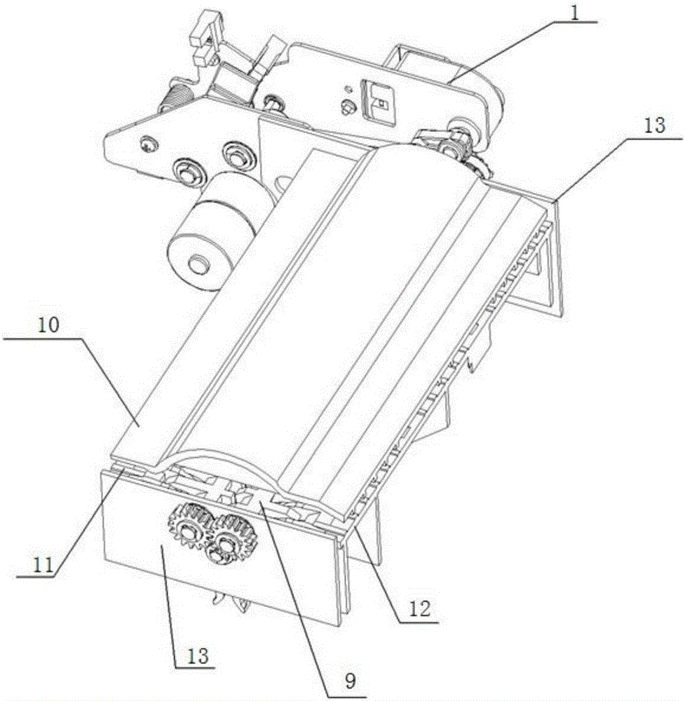
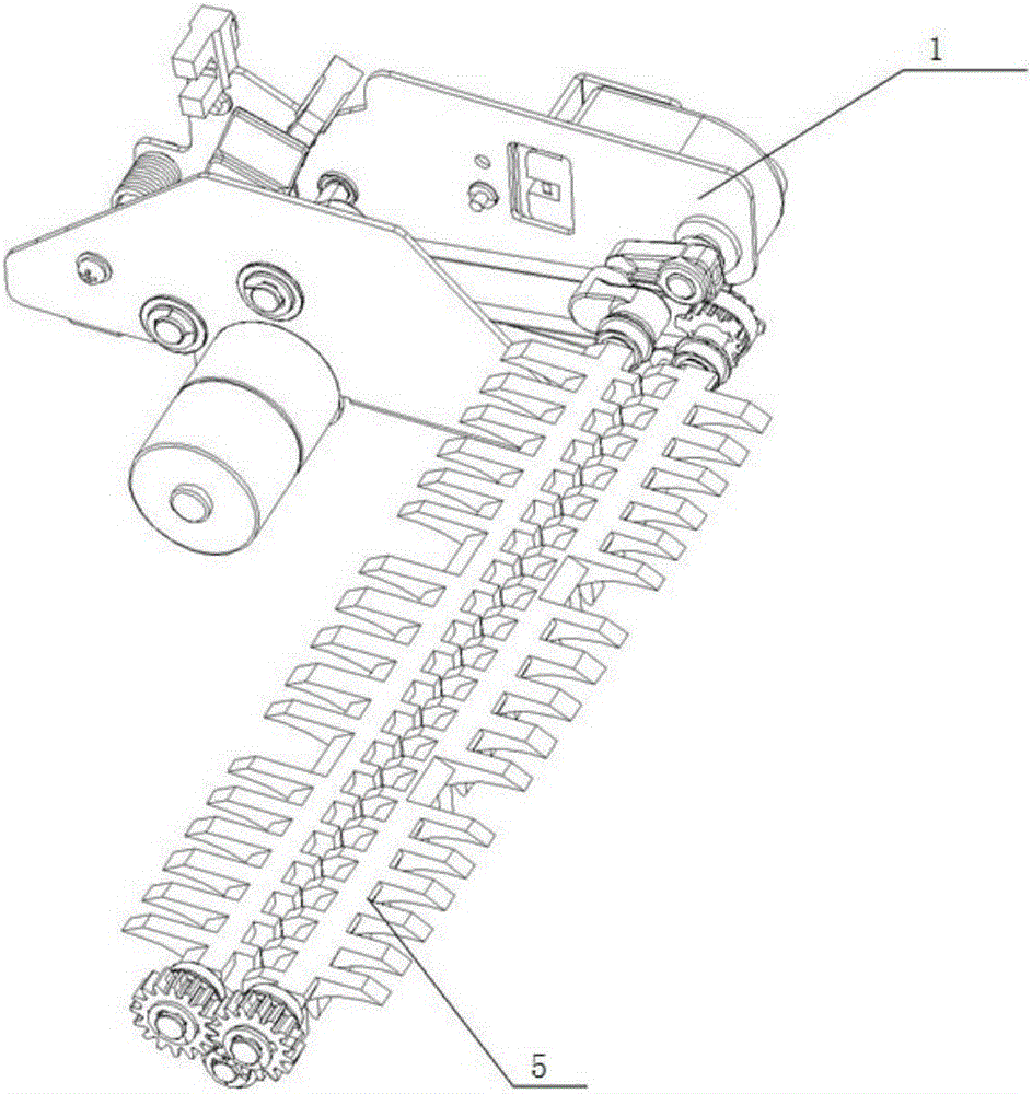
[0033] Such as Figure 7 As shown, when the first reversing blade assembly 4, the second reversing blade assembly 5, and the third reversing blade assembly 6 are in the positions shown in the figure, the first reversing blade assembly 4 and the second reversing blade assembly The contours of 5 and the third reversing blade assembly 6 and the upper channel 10, the left channel 11 and the right channel 12 form a linear conveying channel path from left to right or from right to left of the sheet, that is, banknotes.

Embodiment 2

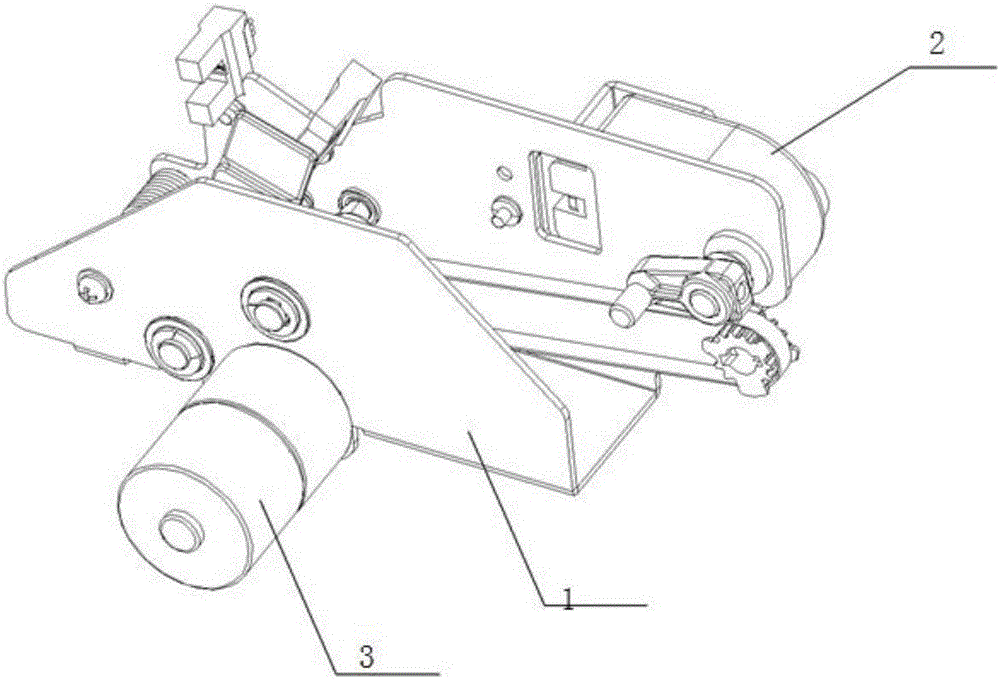
[0035] Such as Picture 8 As shown, when the first reversing blade assembly 4, the second reversing blade assembly 5, and the third reversing blade assembly 6 are in the positions shown in the figure, the first reversing blade assembly 4, the second reversing blade assembly 5 and the contours of the third reversing blade assembly 6 and the upper channel 10, the left channel 11, and the right channel 12 form a curved conveying channel path from left to bottom or from bottom to left of the sheet, that is, banknotes. This embodiment The state of the reversing blade assembly in the example is formed by the symmetrical relative rotation of the first reversing blade assembly 4 and the second reversing blade assembly 5 through the rotation of the two-way electromagnet 2-1 in the first embodiment.

Embodiment 3

[0037] Such as Picture 9 As shown, when the first reversing blade assembly 4, the second reversing blade assembly 5, and the third reversing blade assembly 6 are in the positions shown in the figure, the first reversing blade assembly 4, the second reversing blade assembly 5 and the contours of the third reversing blade assembly 6 and the upper channel 10, the left channel 11, and the right channel 12 form a curved conveying channel path from right to bottom or from bottom to right of the sheet, that is, banknotes. This embodiment The state of the reversing blade assembly in the example is formed by the rotation of the power motor 3-1 in the second embodiment to drive the rotation of the third reversing blade assembly 6.


PUM


Abstract

The invention discloses a guider for flaky object conveying, comprising a reversing blade assembly, a power drive assembly matching the reversing blade assembly, and a channel arranged outside the reversing blade assembly. The power drive assembly comprises a power drive assembly frame, a two-way electromagnet assembly and a power motor assembly. The two-way electromagnet assembly and the power motor assembly are arranged on the power drive assembly frame. The two-way electromagnet assembly and the power motor assembly drive the power drive assembly to rotate and reverse. The reversing blade assembly and the channel form a conveying channel when the reversing blade assembly rotates and reverses. The guider for flaky object conveying has the advantages of reasonable and simple structure design, low production cost, easy-to-control precision, and easy operation.

Description

Technical field [0001] The invention relates to a guide for conveying sheets, in particular to a guide for conveying sheets for conveying banknotes. Background technique [0002] The existing sheet guide generally has three driving devices, which are a stepping motor and two lifting magnets. The working process is as follows: the stepping motor drives the driving rod to rotate through two driving wheels, and the driving rod There are gears on the two ends of the guide, and the two guide plates of the guide are integrally provided with racks. During the rotation of the driving rod, the gears and the racks are driven to drive the entire guide plate to move up and down. The blades are arranged on the guide plate, so the lifting of the guide plate realizes the lifting of the guide blade, thereby realizing the reversal of the two side channels. From the above working process, it can be seen that only the reversal between the two side channels is Many transmission components are invol...

Claims


Application Information

Patent Timeline
Patent Type & Authority Applications(China)
IPC IPC(8): G07D11/00B65H5/36B65H29/54
CPCG07D11/16B65H5/36B65H29/54B65H29/58B65H2404/632B65H2701/1912B65H2403/42B65H2301/3125
Inventor 阮卓光苏全廖任吴恩
Owner 广州智清电子科技有限公司
Learn More