Roller and machining technology thereof

A processing technology and roller technology, which is applied in the direction of rotary printing machine, printing, printing machine, etc., can solve the problem of high stress at the connection between the main shaft and the side plate, etc.

Inactive Publication Date: 2019-03-26
刘长江
View PDF0 Cites 0 Cited by
  • Summary
  • Abstract
  • Description
  • Claims
  • Application Information

AI Technical Summary

Problems solved by technology

[0004] The purpose of the present invention is to propose a drum, which mainly solves the problem of excessive stress at the joint between the main shaft and the side plate, is suitable for the processing of drums requiring high precision, can improve the quality and precision of drum processing, and has a process simple advantage

Method used


Image

  • Roller and machining technology thereof
  • Roller and machining technology thereof

Examples


Embodiment Construction

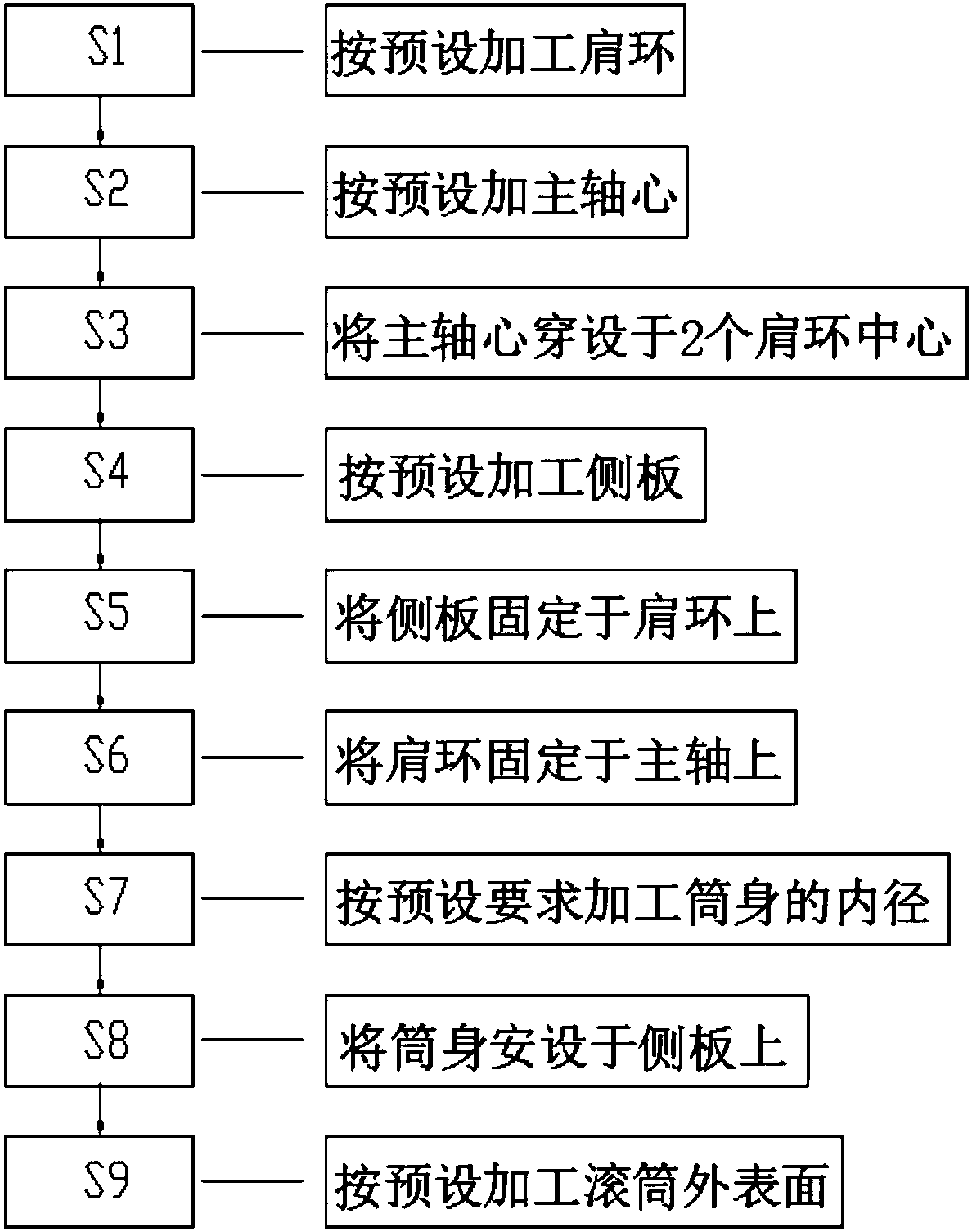
[0022] The technical solutions of the present invention will be further described below in conjunction with the drawings and specific implementations.

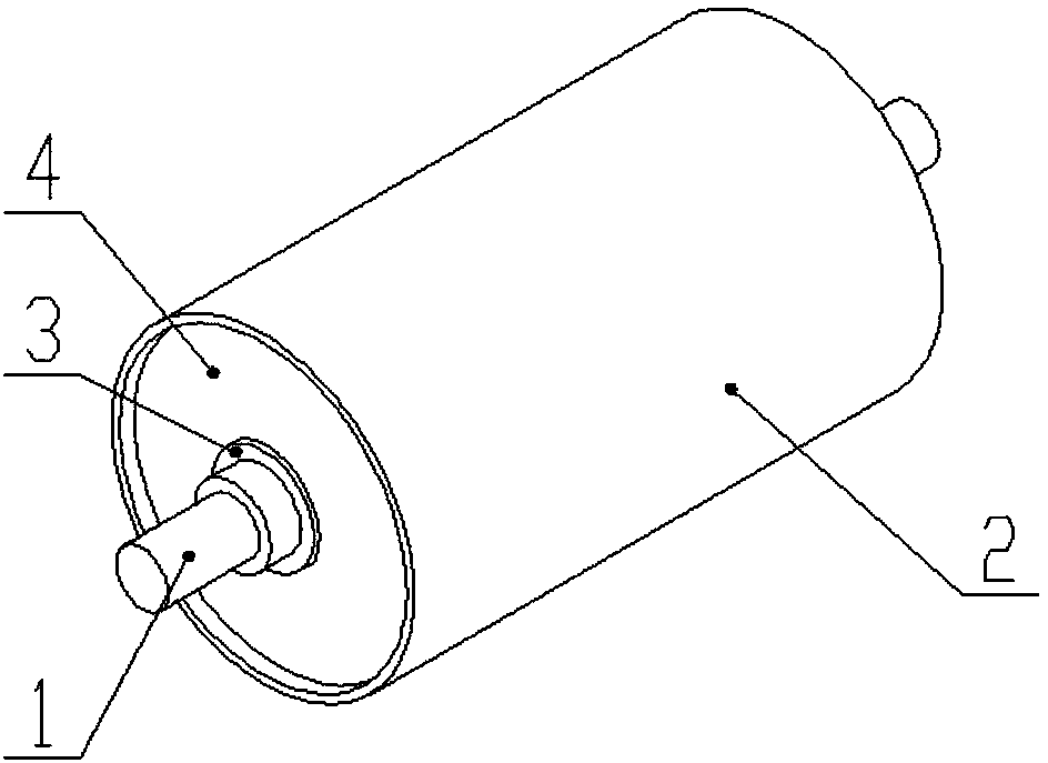
[0023] Such as figure 1 As shown, the roller provided by this application mainly solves the problem of excessive stress at the connection between the main shaft and the side plate, is suitable for the processing of rollers with high-precision requirements, can improve the quality and accuracy of roller processing, and has processing The advantage of simple process.

[0024] The above-mentioned drum includes a barrel 02, a side plate 04 arranged on the side plate shoulder ring 03, and a main shaft 01 passing through the two shoulder rings; the barrel 02 is supported by two side plates 04 inside.

[0025] The side plate shoulder ring is inserted through the middle of the side plate 04, and is fixed by welding after positioning;

[0026] The mating part of the main shaft 01 and the two side plate shoulder rings is a conical type fastenin...


PUM


Abstract

The invention discloses a roller and a machining technology thereof. The roller comprises a roller body, lateral plates arranged on lateral plate shoulder rings, and a spindle penetrating through theshoulder rings. The interior of the roller body is supported by the two lateral plates. Two ends of the spindle are matched with the two lateral plate shoulder rings. The sizes of the outer ring of the shoulder rings are same. A machining mode of the roller is provided, and a novel machining mode is provided for the roller machining technology. The roller is machined in a kit mode. The quality ofthe roller is improved, the service life is prolonged, and stability is improved.

Description

Technical field [0001] The processing technology field of the present invention particularly relates to a roller and its processing technology. Background technique [0002] When we process some special mechanisms, we will encounter places where large rollers are needed, such as the transmission part of the conveyor belt of sand mining equipment, and the transmission roller on the printing equipment. The quality of these rollers will affect the quality and service life of the equipment itself. [0003] The most common problem during use is that the link between the main shaft and the side plate is broken. This link is the position where the entire main shaft is most stressed, and the thickness of the side plate generally only considers the force on the weighing drum and the load, but does not consider the force on the link between the main shaft and the side plate. The load force of the entire roller is concentrated at this position. In this regard, we invented a roller and proc...

Claims


Application Information

Patent Timeline
Patent Type & Authority Applications(China)
IPC IPC(8): B23P15/00B41F13/08E21C47/10
CPCB23P15/00B41F13/08E21C47/10
Inventor 刘长江
Owner 刘长江
Why Eureka
Try Eureka