Automobile tire rapid maintenance and correction device

An automobile tire and fast technology, applied in tire installation, wheel assembly and disassembly equipment, wheels, etc., can solve the problem of automobile tires being unable to be automated, and achieve the effect of tire maintenance and correction, automatic handling, and labor intensity reduction.

Active Publication Date: 2019-03-26
HUNAN ELECTRICAL COLLEGE OF TECH
View PDF6 Cites 13 Cited by
  • Summary
  • Abstract
  • Description
  • Claims
  • Application Information

AI Technical Summary

Problems solved by technology

[0004] The purpose of the present invention is to solve the problem that automobile tires cannot be automatically and conveniently transported and repaired and corrected during rapid maintenance, and propose a rapid repair and correction device for automobile tires

Method used


Image

  • Automobile tire rapid maintenance and correction device
  • Automobile tire rapid maintenance and correction device
  • Automobile tire rapid maintenance and correction device

Examples


Embodiment 1

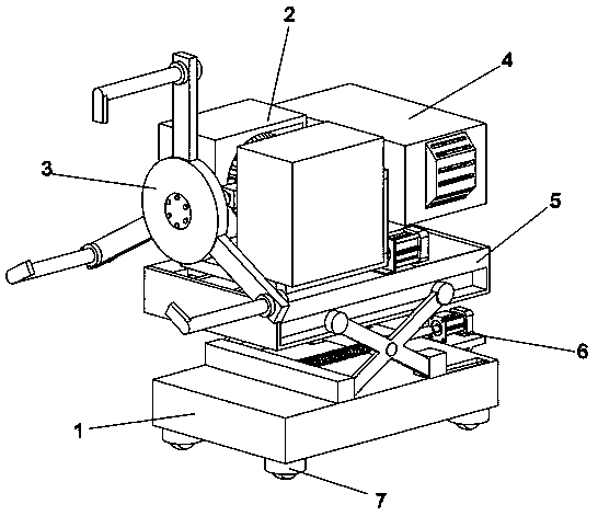
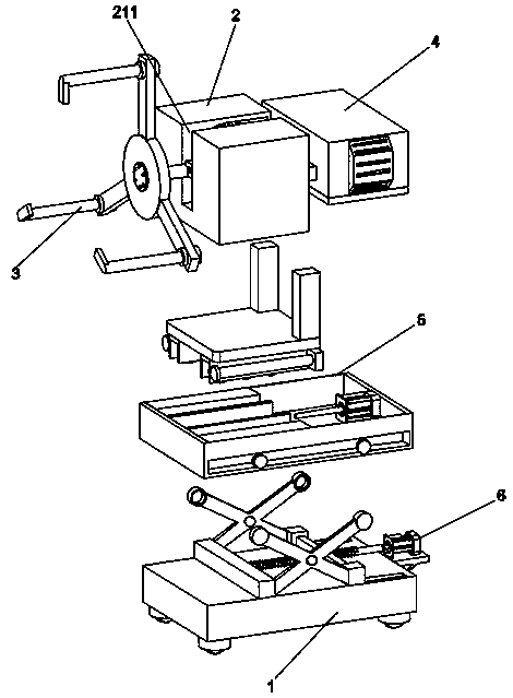
[0044] A rapid repair and correction device for automobile tires, including a mobile base 1, characterized in that it also includes:

[0045] Lifting component 6, the lifting component 6 is arranged on the upper surface of the mobile base 1, and the lifting component 6 is used for lifting the Y-axis rotation mechanism 2, the tire clamping component 3, the power output mechanism 4 and the Z-axis adjustment mechanism 5;

[0046] The Z-axis adjustment mechanism 5, the Z-axis adjustment mechanism 5 is arranged above the lifting assembly 6, and the Z-axis adjustment mechanism 5 is used to adjust the positions of the Y-axis rotation mechanism 2, the tire clamping assembly 3 and the power output mechanism 4 in the Z-axis direction;

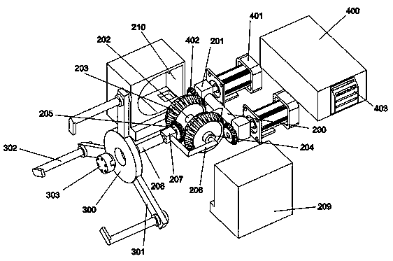
[0047] Y-axis rotation mechanism 2, Y-axis rotation mechanism 2 is arranged on the top of Z-axis adjustment mechanism 5, and Y-axis rotation mechanism 2 is used to rotate the position of tire clamping assembly 3 in the Y-axis direction, and adjust tire cl...

Embodiment 2

[0053] Embodiment 2: the difference based on Embodiment 1 is;

[0054] Lifting assembly 6 includes: motor mounting frame 600, decelerating motor 601, T-shaped screw rod 602, linear bearing rod 603, screw rod connecting block 604, cross plate 605, pin shaft 606, reinforcing rod 607, guide groove 608 and lifting bracket 609;

[0055] The rear end of the mobile base 1 is fixedly provided with a motor mounting frame 600, and the top surface of the motor mounting frame 600 is fixedly mounted with a geared motor 601. The outer thread is connected with a screw connection block 604, and the rear end of the top surface of the mobile base 1 is symmetrically provided with two guide grooves 608, and a linear bearing rod 603 is fixedly arranged in the guide groove 608, and the two ends of the screw connection block 604 are connected with two straight lines respectively. The bearing rod 603 is socketed, and the middle part of the top surface of the mobile base 1 is also fixedly provided wi...

Embodiment 3

[0058] Embodiment 3: the difference based on embodiment 1 and 2 is;

[0059] The Z-axis adjustment mechanism 5 includes: an installation box 500, a rotating block 501, a cylinder 502, a slide groove 503, a strip groove 504 and a limit groove 505;

[0060] The outer sides of the left and right ends of the installation box 500 are symmetrically provided with two rotating blocks 501, the inner ends of the rotating blocks 501 are slidingly connected with the side surfaces of the installation box 500, and the outer sides of the rotating blocks 501 are rotationally connected with the inner sides of the upper ends of the reinforcing rods 607. After the installation of the box body 500 A cylinder 502 is fixedly installed on the inner wall of the end, and a strip groove 504 is provided in the middle position of the installation box 500, and two slide grooves 503 are symmetrically opened on the left and right sides of the strip groove 504 in the installation box 500. A limiting groove 5...


PUM


Abstract

The invention discloses an automobile tire rapid maintenance and correction device and belongs to the technical field of automobile maintenance. The automobile tire rapid maintenance and correction device comprises a mobile base, a Y-axis rotating mechanism, a tire clamping component, a power output mechanism, a Z-axis adjusting mechanism and a lifting component. According to the automobile tire rapid maintenance and correction device, as the lifting component is arranged on the top surface of the mobile base, the clamping height of the tire clamping component to an automobile tire can be adjusted by using the lifting component to enable the automobile tire to be conveyed or mounted conveniently; and moreover, the power is output by using the power output mechanism above the lifting component so that the Y-axis rotating mechanism operates; and finally, a wheel clamped by the tire clamping component is pushed to a wheel assembly direction by using the Z-axis adjusting mechanism to finish docking of the automobile tire and a wheel assembly. According to the automobile tire rapid maintenance and correction device, the labor intensity of maintenance worker is effectively reduced, a multi-dimension correction demand is also provided for automobile tire rapid maintenance so as to realize automobile tire automatic conveying and tire maintenance and correction, and therefore, the working efficiency is enhanced.

Description

technical field [0001] The invention relates to the technical field of automobile maintenance, in particular to a rapid repair and correction device for automobile tires. Background technique [0002] Vehicle maintenance and repair is a general term for vehicle maintenance and repair. It is to check the faulty car through technical means to find out the cause of the fault, and take certain measures to eliminate the fault and restore it to a certain performance and safety standard. Automobile maintenance includes automobile overhaul and automobile minor repair. Automobile overhaul refers to the method of repairing or replacing any parts (including basic parts) of the automobile to restore the complete technical condition of the automobile and completely (or nearly completely) restore the restorative repair of the life of the automobile. Automobile minor repair refers to the operational repair of ensuring or restoring the working ability of the automobile by replacing or repa...

Claims


Application Information

Patent Timeline
Patent Type & Authority Applications(China)
IPC IPC(8): B60B29/00
CPCB60B29/001
Inventor 刘珊周志明朱建军何丽嘉
Owner HUNAN ELECTRICAL COLLEGE OF TECH
Why Eureka
Try Eureka