
A fully automatic bucket elevator for material conveying

A fully automatic, bucket elevator technology, applied in the direction of conveyors, conveyor objects, conveyor control devices, etc., can solve problems such as waste of labor, troublesome operation, etc., to achieve the effect of promoting smooth sliding, easy implementation, and avoiding blockage

Active Publication Date: 2020-11-17
ZHENGZHOU JINCHENG CHENGXIN SCREEN EQUIP CO LTD
View PDF5 Cites 0 Cited by
  • Summary
  • Abstract
  • Description
  • Claims
  • Application Information

AI Technical Summary

Problems solved by technology

[0005] The purpose of the present invention is: in order to solve the technical problem that the existing bucket elevator manually digs out the material spilled during the conveying process and then adds it to the feeding hopper, the operation is troublesome and the labor is wasted, the present invention provides a fully automatic material conveying Bucket elevator

Method used


Image

  • A fully automatic bucket elevator for material conveying
  • A fully automatic bucket elevator for material conveying
  • A fully automatic bucket elevator for material conveying

Examples


Embodiment 1

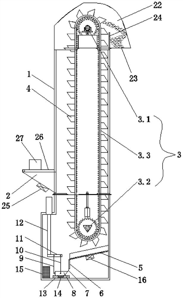
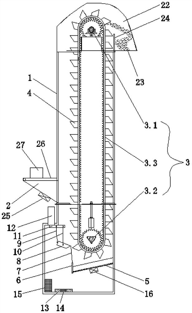
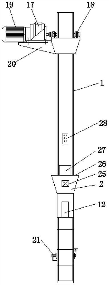
[0033] Such as Figures 1 to 3 As shown, the present embodiment provides a fully automatic bucket elevator for material transportation, including a casing 1, a feed hopper 2 is provided at the side end of the casing 1, and a bucket 2 is provided in the casing 1 for moving materials from a low place to a high place. The chain conveying mechanism 3 for transportation, the outer edge of the chain conveying mechanism 3 is provided with several transport hoppers 4, the housing 1 is provided with a collecting tank 5 located below the chain conveying mechanism 3, and the collecting groove 5 faces the direction of the feeding hopper 2 Inclined downward, one end of the collecting tank 5 inclined downward is hinged with a blocking plate 6, the blocking plate 6 is connected with an elastic stay cord 7, and the other end of the elastic stay cord 7 is connected with a collection box 8 located directly below the outlet of the collecting tank 5 , the other side end of the collection box 8 is c...

Embodiment 2

[0036] Such as Figures 1 to 2 As shown, this embodiment is further optimized on the basis of Embodiment 1. Specifically, a base 13 is provided at the inner bottom of the casing 1, the collection box 8 is located on the base 13, and the collection box 8 is located on the base 13. 8 The weight sensor 14 at the bottom, the central processor 15 is arranged in the casing 1, and the central processor 15 is electrically connected with the weight sensor 14 and the telescopic cylinder 12 at the same time.

[0037] In this embodiment, when the material in the collecting box reaches a certain weight, the weight sensor sends a signal to the central processor, and the central processor processes the signal and then sends an instruction to the telescopic cylinder, and the telescopic cylinder begins to complete a "shrink-extend" "Long" working stroke, so as to complete the process of conveying the spilled materials, with a high degree of intelligence and easy implementation.

Embodiment 3

[0039] Such as figure 1 with 4 As shown, this embodiment is further optimized on the basis of embodiment 1. Specifically, the vertical section of the collection tank 5 is U-shaped, and the bottom of the collection tank 5 is provided with a first vibrator 16 .

[0040] In this embodiment, the U-shaped collecting trough is beneficial to gather the materials at the bottom of the collecting trough, which is convenient for guiding the materials. The first vibrator generates a sense of vibration to the collecting trough, so that the materials can slide smoothly into the collecting box below, avoiding Material is clogged.


PUM


Abstract

The invention discloses a full-automatic bucket elevator for material conveying, and relates to the technical field of bucket elevators. The full-automatic bucket elevator comprises a machine case, afeeding hopper is arranged at the side end of the machine case, a chain conveying mechanism used for conveying materials from the low position to the high position is arranged in the machine case, theedge of the chain conveying mechanism is provided with a plurality of conveying hoppers, the machine case is internally provided with a collecting groove located below the chain conveying mechanism,the collecting groove is inclined downwards towards the feeding hopper, a plugging plate is hinged to the downwards-inclined end of the collecting groove and is connected with an elastic pull rope, the other end of the elastic pull rope is connected with a collecting box located under an outlet of the collecting groove, the other side end of the collecting box is connected with a first pulling rope, second pulling ropes are connected to the front and rear ends of the collecting box, the first pulling rope and the second pulling ropes are connected with a hanging plate located above the collecting box, a telescopic cylinder arranged on the machine case is connected to the top of the hanging plate, and the telescopic cylinder is located below the feeding hopper. The full-automatic bucket elevator has the advantages of being simple in structure, saving the labor force and being high in degree of automation.

Description

technical field [0001] The invention relates to the technical field of bucket elevators, in particular to a fully automatic bucket elevator for material transportation. Background technique [0002] Bucket elevator, that is, bucket elevator, bucket elevator is a continuous conveying machine that uses a series of hoppers evenly fixed on the endless traction member to lift materials vertically. Or the hopper on the belt transports the bulk material upwards in the vertical or near vertical direction, which is divided into three types: ring chain, plate chain and belt. Its working principle is: the hopper scoops up the material from the storage below, lifts it to the top along with the conveyor belt or chain, bypasses the top wheel and then turns down, the bucket elevator pours the material into the receiving tank, and the belt drive The transmission belt of the bucket elevator is generally a rubber belt, which is installed on the lower or upper driving drum and the upper and l...

Claims


Application Information

Patent Timeline
Patent Type & Authority Patents(China)
IPC IPC(8): B65G17/12B65G17/36B65G17/30B65G17/38B65G47/40B65G43/08
CPCB65G17/126B65G17/30B65G17/36B65G17/38B65G43/08B65G47/40B65G2203/042
Inventor 高建芳管旭
Owner ZHENGZHOU JINCHENG CHENGXIN SCREEN EQUIP CO LTD
Learn More