
Combustion system and overhead regenerative burner

A heat storage type and burner technology, which is applied in the direction of gas fuel burner, burner, combustion type, etc., can solve the problems of explosion hazard, combustion-supporting air inaccessibility, insufficient fuel combustion, etc.

Pending Publication Date: 2019-03-26
广州龙鑫蓄热工业炉有限公司
View PDF0 Cites 2 Cited by
  • Summary
  • Abstract
  • Description
  • Claims
  • Application Information

AI Technical Summary

Problems solved by technology

Workers must be careful when feeding materials, leaving the area of ​​the flame passage, so as not to block the flame nozzle, which will affect the combustion effect, or even cause the furnace to explode, resulting in the inability to fully utilize the furnace space.
[0003] For traditional regenerative burners, the design elevation of the burner is 200mm to 300mm above the aluminum liquid level. During the operation of the aluminum melting furnace, no matter the process of feeding and stirring, slag and ash removal, degassing and refining, combustion and suction , there will always be the phenomenon that aluminum water and aluminum slag splash to the crater. Over time, the phenomenon of slag accumulation in the crater will become more and more serious, and the area of ​​the crater channel will become smaller and smaller. Insufficient combustion, black smoke from the furnace door, and higher and higher energy consumption, so the furnace had to be shut down to remove slag. This is also a common problem of traditional regenerative burners and cannot be completely solved.
[0004] The regenerator of the traditional regenerative burner is installed at the bottom, and the smoke is discharged downward. When the dusty flue gas in the furnace passes through the regenerative burner downward, it is blocked by the surface heat storage ball and stays in the heat storage ball. The surface of the heat storage ball will accumulate more and more, causing the heat storage ball to accumulate dust and harden, increasing the resistance of air and smoke to penetrate the heat storage ball, seriously affecting the combustion effect

Method used


Image

  • Combustion system and overhead regenerative burner
  • Combustion system and overhead regenerative burner
  • Combustion system and overhead regenerative burner

Examples


Embodiment Construction

[0030] In order to make the above objects, features and advantages of the present invention more comprehensible, specific implementations of the present invention will be described in detail below in conjunction with the accompanying drawings. In the following description, numerous specific details are set forth in order to provide a thorough understanding of the present invention. However, the present invention can be implemented in many other ways different from those described here, and those skilled in the art can make similar improvements without departing from the connotation of the present invention, so the present invention is not limited by the specific implementations disclosed below.

[0031] It should be noted that when an element is referred to as being “fixed” to another element, it can be directly on the other element or there can also be an intervening element. When an element is referred to as being "connected to" another element, it can be directly connected ...


PUM


Abstract

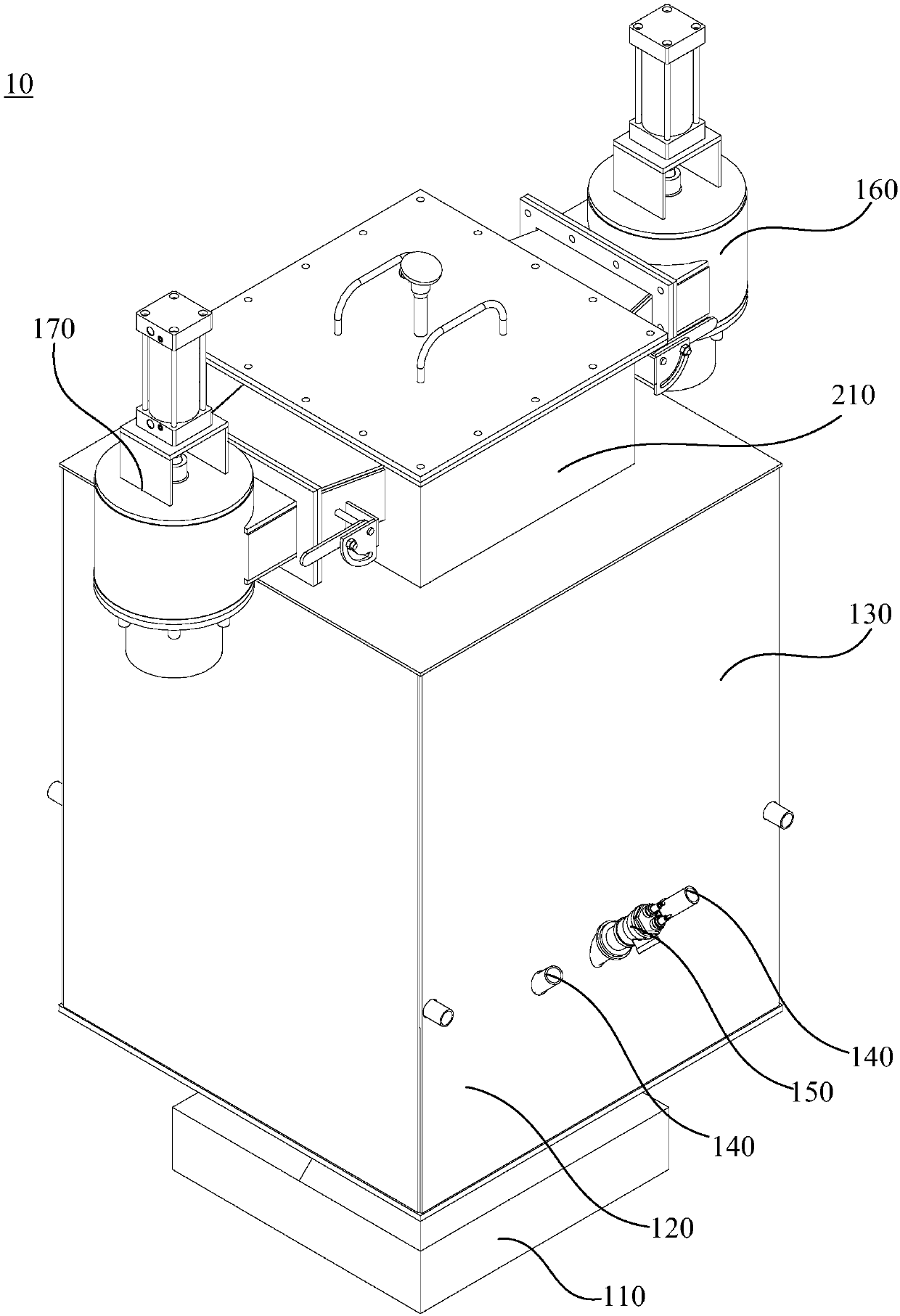
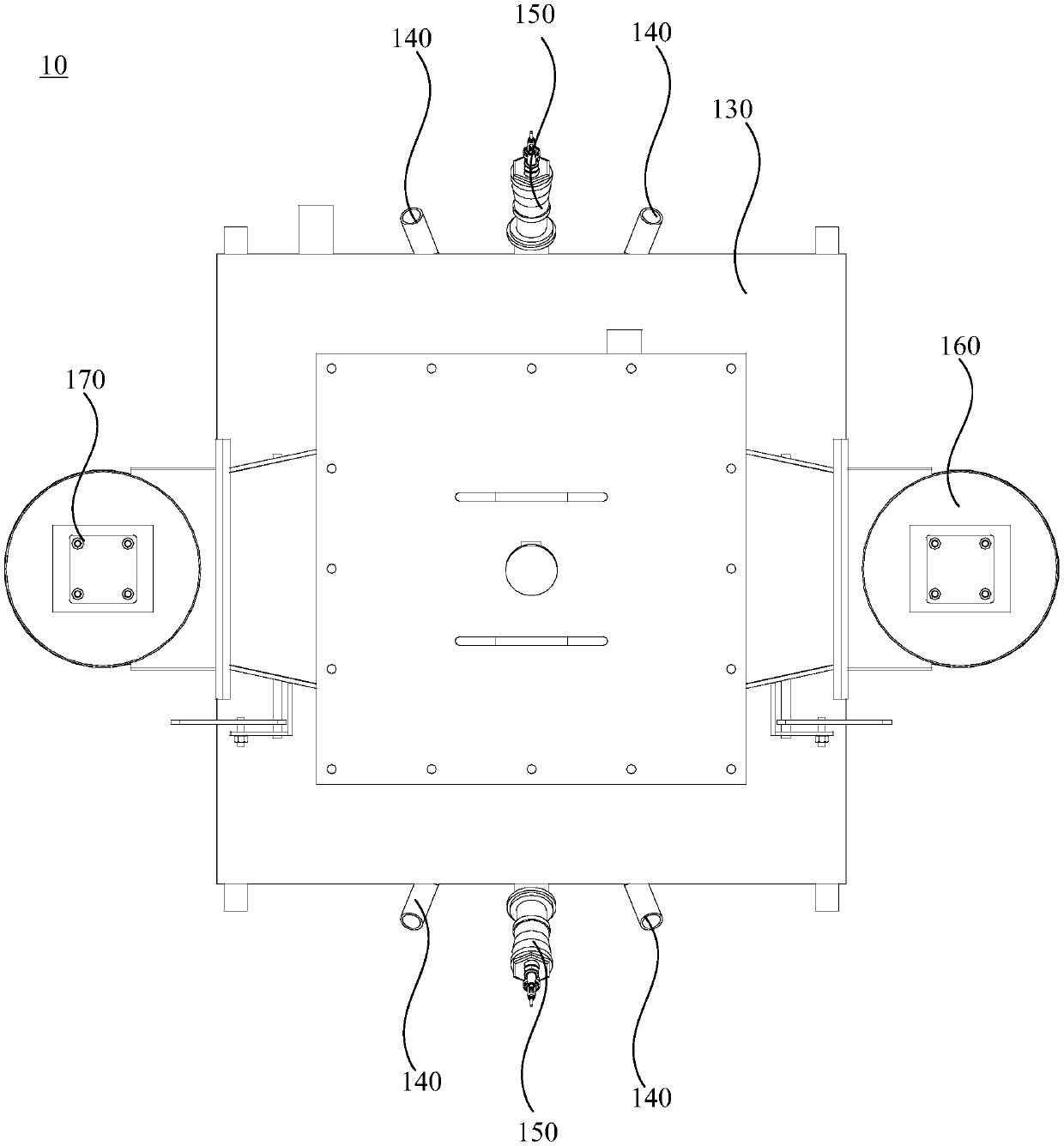
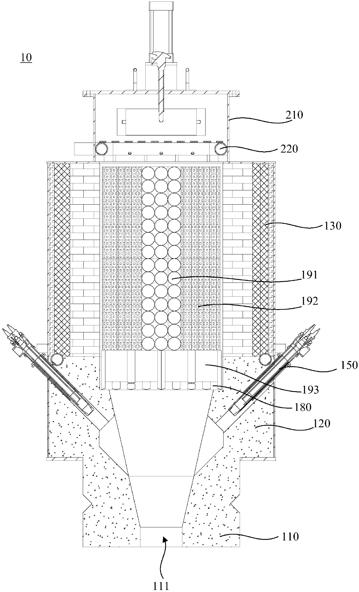
The invention relates to a combustion system and an overhead regenerative burner. The overhead regenerative burner comprises a nozzle, a combustion chamber, a heat accumulation chamber, a main fuel burner, an ignition burner, combustion-supporting air valves and smoke exhaust valves. According to the combustion system and the overhead regenerative burner, the nozzle downwards extends in the direction vertical to the top of a stove, so that flames sprayed from a fire spraying opening are downwards sprayed into a hearth in the direction vertical to the top of the stove, a flame channel does notneed to be reserved, hearth feeding is not limited, and the hearth space can be fully relieved and is fully utilized; molten aluminum and aluminum slags are not gathered at the fire spraying opening,the fire spraying opening is always clean and smooth, the problem that the slags are accumulated at the fire spraying hole is solved; and accumulated dust in heat accumulators can be automatically cleared without external power, and the function of prolonging the service life and maintenance period of the heat accumulators is achieved.

Description

technical field [0001] The invention relates to the technical field of fuel combustion devices for industrial furnaces, in particular to a combustion system and an overhead regenerative burner. Background technique [0002] Most of the traditional regenerative burners are down-mounted regenerative burners installed on the side wall, and the flame is sprayed into the furnace horizontally and horizontally at an inclination angle of 15 degrees to 20 degrees. Workers must be careful when feeding materials, leaving the area of ​​the flame passage, so as not to block the flame nozzle with the injected materials, which will affect the combustion effect, and even cause the danger of furnace explosion, resulting in the inability to fully utilize the furnace space. [0003] For traditional regenerative burners, the design elevation of the burner is 200mm to 300mm above the aluminum liquid level. During the operation of the aluminum melting furnace, no matter the process of feeding and...

Claims


Application Information

Patent Timeline
IPC IPC(8): F23D14/00F23D14/46F23D14/48
CPCF23D14/00F23D14/46F23D14/48
Inventor 郭志明伍韵洁
Owner 广州龙鑫蓄热工业炉有限公司
Learn More