Positioning drift detecting method and device
A technology for drift detection and positioning position, which is applied in the field of positioning and can solve problems such as reflection, phase, time change, and large difference in positioning position.
- Summary
- Abstract
- Description
- Claims
- Application Information
AI Technical Summary
Problems solved by technology
Method used
Image
Examples
Embodiment 1
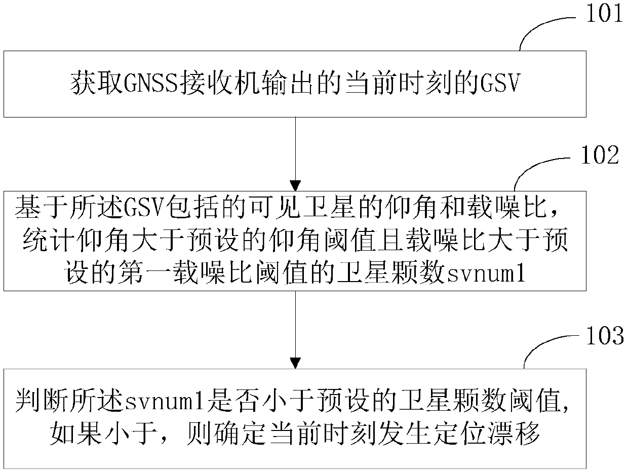
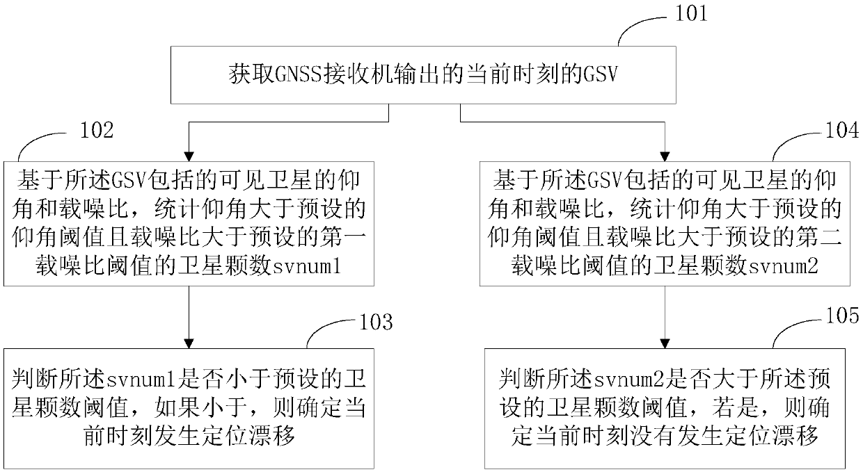
[0124] Embodiment 1 of the present application provides a positioning drift detection method, such as Figure 1a As shown, the methods include:
[0125] Step 101, acquire the GSV at the current moment output by the GNSS receiver.
[0126]GSV includes the elevation angle ELE and CNO (also C / No, carrier-to-noise ratio, carrier-to-noise ratio) of each visible satellite among the multiple satellites that can be observed.
[0127] Step 102, based on the elevation angles and carrier-to-noise ratios of visible satellites included in the GSV, count the number svnum1 of satellites whose elevation angles are greater than a preset elevation angle threshold and whose carrier-to-noise ratio is greater than a preset first carrier-to-noise ratio threshold.
[0128] In practical applications, if the elevation angle of a visible satellite is less than 10 degrees, it is considered that the radio frequency signal of the visible satellite is easily reflected by buildings on the ground plane. If t...
Embodiment 2
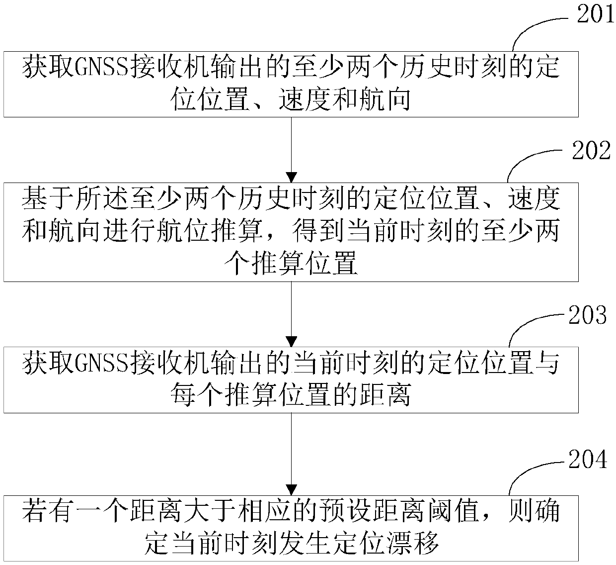
[0141] Embodiment 2 of the present application provides a positioning drift detection method, such as figure 2 As shown, the methods include:
[0142] Step 201, acquire the positioning position, velocity and heading outputted by the GNSS receiver at least two historical moments.
[0143] In this embodiment of the present application, the positioning position, velocity and heading of at least two historical moments can be obtained from the RMC output by the GNSS receiver. Wherein, the positioning position includes longitude lon0 and latitude lat0, speed is spd0, and heading is cog0.
[0144] In practical applications, the output frequency of the GNSS receiver can be flexibly set, generally set to 1Hz, that is, a string of information is output per second, and the acquisition of the RMC output by the GNSS receiver can also be performed according to the output frequency of the GNSS receiver, namely , collect and store the positioning position, speed and heading output by the G...
Embodiment 3
[0170] Implementation 3 of this application provides a positioning drift detection method, such as image 3 As shown, the methods include:
[0171] Step 301 , based on the identifiers of the satellites participating in the current positioning included in the GSA information, the current carrier-to-noise ratio of the satellites participating in the positioning at the current moment is obtained from the GSV.
[0172] Step 302, acquiring the historical carrier-to-noise ratio of the satellites participating in the positioning at the current moment at the previous moment.
[0173] Step 303, obtaining the difference between the current carrier-to-noise ratio and the historical carrier-to-noise ratio of the satellites participating in the positioning at the current moment.
[0174] Step 304, counting the number svnum3 of satellites whose difference is greater than the preset change threshold of carrier-to-noise ratio.
[0175] The preset change threshold of the carrier-to-noise rat...
PUM
 Abstract
Description
Claims
Application Information
 - R&D
- Intellectual Property
- Life Sciences
- Materials
- Tech Scout
- Unparalleled Data Quality
- Higher Quality Content
- 60% Fewer Hallucinations
Browse by: Latest US Patents, China's latest patents, Technical Efficacy Thesaurus, Application Domain, Technology Topic, Popular Technical Reports.
© 2025 PatSnap. All rights reserved.Legal|Privacy policy|Modern Slavery Act Transparency Statement|Sitemap|About US| Contact US: help@patsnap.com


