Virtual image imaging system with anti-peep film

An imaging system and anti-peeping film technology, which is applied in optics, instruments, optical components, etc., can solve the problem that virtual images cannot be presented, and achieve the effect of improving optical imaging quality and stability

Pending Publication Date: 2019-03-26
HANGZHOU FERVCLOUD TECHNOLOGY CO LTD
View PDF8 Cites 4 Cited by
  • Summary
  • Abstract
  • Description
  • Claims
  • Application Information

AI Technical Summary

Problems solved by technology

Firstly, the virtual image is formed by converging the reverse extension lines of the actual light; secondly, the virtual image cannot be presented on the light screen at this position, and can only be observed through optical elements

Method used


Image

  • Virtual image imaging system with anti-peep film
  • Virtual image imaging system with anti-peep film
  • Virtual image imaging system with anti-peep film

Examples


Embodiment 1

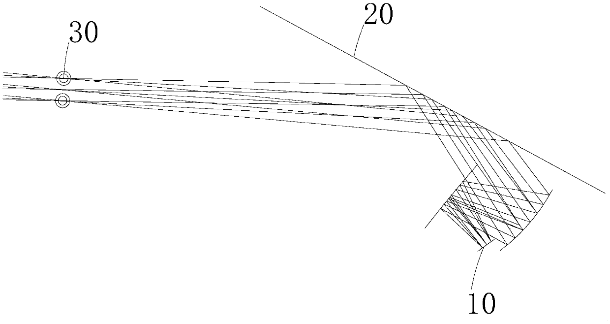
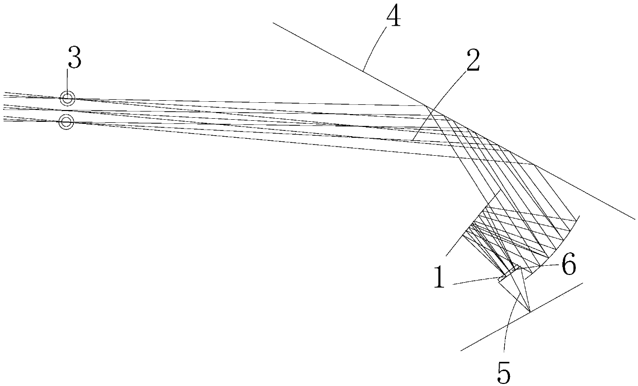
[0024] Such as Figure 1-4 As shown, the present invention provides a technical solution: a virtual image imaging system with an anti-peeping film, including an image source module 1, a lens 2 in the imaging system, an observer position 3, a light trajectory 4, and an outgoing light 5 and the anti-peeping film 6, the imaging light emitted by the image source module 1 is reflected by the lens 2 in the imaging system, the light trace 4 is the imaging light, and the light trace 4 is reflected to the observer position 3 by the lens 2 in the imaging system, The image source module 1 includes the outgoing light 5, and the trajectory direction of the outgoing light 5 is opposite to that of the light trajectory 4. The anti-peeping film 6 is pasted on the outer surface directly in front of the image source module 1, and the outgoing light 5 is the imaging Stray light generated in the system.

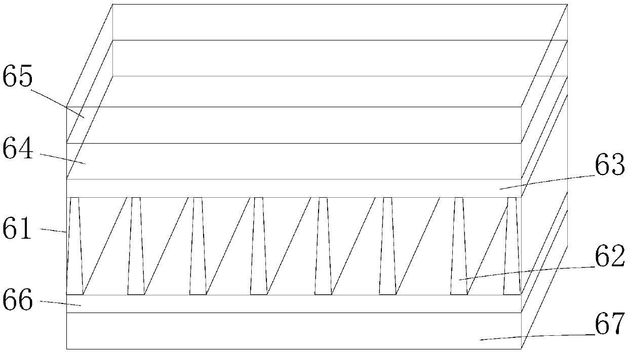
[0025] The anti-peeping film 6 includes a base film 61, a lattice grating 62, an inner reces...

Embodiment 2

[0028] The image source module 1 of the virtual image imaging system can be a polarized image source, such as a liquid crystal screen, or a non-polarized image source.

[0029] A virtual image imaging system with an anti-peeping film, comprising an image source module 1, a lens 2 in the imaging system, an observer position 3, a light trajectory 4, outgoing light 5 and an anti-peeping film 6, the image source module 1 The emitted imaging light is reflected by the lens 2 in the imaging system, the ray trace 4 is the imaging ray, the ray trace 4 is reflected to the observer position 3 through the lens 2 in the imaging system, the image source module 1 contains the outgoing light 5, and The trajectory direction of the outgoing light 5 is opposite to that of the light trajectory 4. The anti-peeping film 6 is pasted on the outer surface directly in front of the image source module 1. The outgoing light 5 is the stray light generated in the imaging system.

[0030]The anti-peeping fi...

Embodiment 3

[0032] According to the design and requirements of different virtual image imaging systems, privacy films with different light filtering properties can be used.

[0033] A virtual image imaging system with an anti-peeping film, comprising an image source module 1, a lens 2 in the imaging system, an observer position 3, a light trajectory 4, outgoing light 5 and an anti-peeping film 6, the image source module 1 The emitted imaging light is reflected by the lens 2 in the imaging system, the ray trace 4 is the imaging ray, the ray trace 4 is reflected to the observer position 3 through the lens 2 in the imaging system, the image source module 1 contains the outgoing light 5, and The trajectory direction of the outgoing light 5 is opposite to that of the light trajectory 4. The anti-peeping film 6 is pasted on the outer surface directly in front of the image source module 1. The outgoing light 5 is the stray light generated in the imaging system.

[0034] The anti-peeping film 6 i...


PUM


Abstract

The invention relates to the technical field of virtual image imaging systems and discloses a virtual image imaging system with an anti-peep film. The system comprises an image source module, a lens in the imaging system, an observer position, a light trajectory, an outgoing light and an anti-peep film. Imaging light emitted by the image source module is reflected by a lens in the imaging system and the light trajectory is imaging light; and the light trajectory is reflected to the observer position by the lens in the imaging system. The image source module includes outgoing light. According to the invention, with the anti-peep film, the image source light is filtered partially by using the film with the anti-peep property, so that the outgoing light direction is controlled and thus the stray light emitted by the image source module is blocked; and thus the direction of the outgoing line of the image source is limited and the outgoing light is filtered. Therefore, special requirementson the incident light, the outgoing line, and the external interference light can be met; and the optical imaging quality of the whole system is improved.

Description

technical field [0001] The invention relates to the technical field of virtual image imaging systems, in particular to a virtual image imaging system with an anti-peeping film. Background technique [0002] A virtual image refers to the collection of points of intersection of the opposite extension lines of light emitted by an object after reflection or refraction. First, the virtual image is formed by converging the reverse extension lines of the actual light; second, the virtual image cannot be presented on the light screen at this position, and can only be observed through optical components. An imaging system with the above characteristics is called a virtual imaging system. Typical virtual imaging systems include: microscopes, telescopes, head-up displays, augmented reality displays, helmet-mounted displays, etc. Images viewed directly through these systems, or through eyepieces, are virtual images. [0003] In a specific virtual image system, due to the special requ...

Claims


Application Information

Patent Timeline
Patent Type & Authority Applications(China)
IPC IPC(8): G02B5/20G02B17/06
CPCG02B17/06G02B5/203
Inventor 王云帆
Owner HANGZHOU FERVCLOUD TECHNOLOGY CO LTD
Why Eureka
Try Eureka