
Underwater self-folding antenna

A technology for folding antennas and bases, which can be used in folding antennas, underwater/underground adaptation, etc., can solve problems such as energy loss, signal reception failure, and affect signal reception strength, and achieve the effect of reducing navigation resistance and saving energy.

Active Publication Date: 2019-03-26
SHENYANG INST OF AUTOMATION - CHINESE ACAD OF SCI
View PDF7 Cites 11 Cited by
  • Summary
  • Abstract
  • Description
  • Claims
  • Application Information

AI Technical Summary

Problems solved by technology

If the iridium antenna, radio antenna, and strobe light are placed inside the aircraft, it will affect the signal reception strength or even fail. For example, the wind and waves at sea are strong, the aircraft fluctuates violently on the water surface, and the antenna is submerged in the water surface, etc. will cause signal reception failure. , so the iridium satellite antennas in the prior art are all installed outside the underwater vehicle, and have a certain height
But on the other hand, when the antenna is fixed on the outside of the aircraft alone, the aircraft will generate greater resistance when navigating underwater, and the water flow will impact the antenna and other devices for a long time, and the antenna may be damaged and affect communication. After the underwater vehicle is submerged, the ship will no longer communicate because it cannot receive the signals from the antenna and other devices. However, the antenna and other devices are still sending out signals, which will consume the limited energy of the underwater vehicle and cause unnecessary energy loss.

Method used


Image

  • Underwater self-folding antenna
  • Underwater self-folding antenna
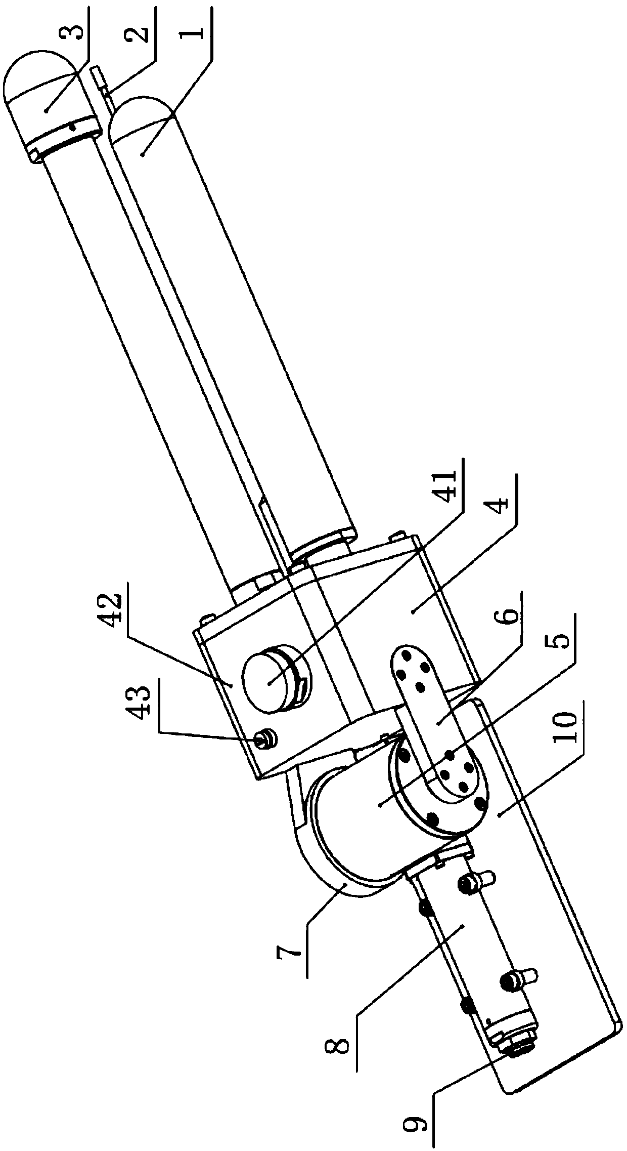
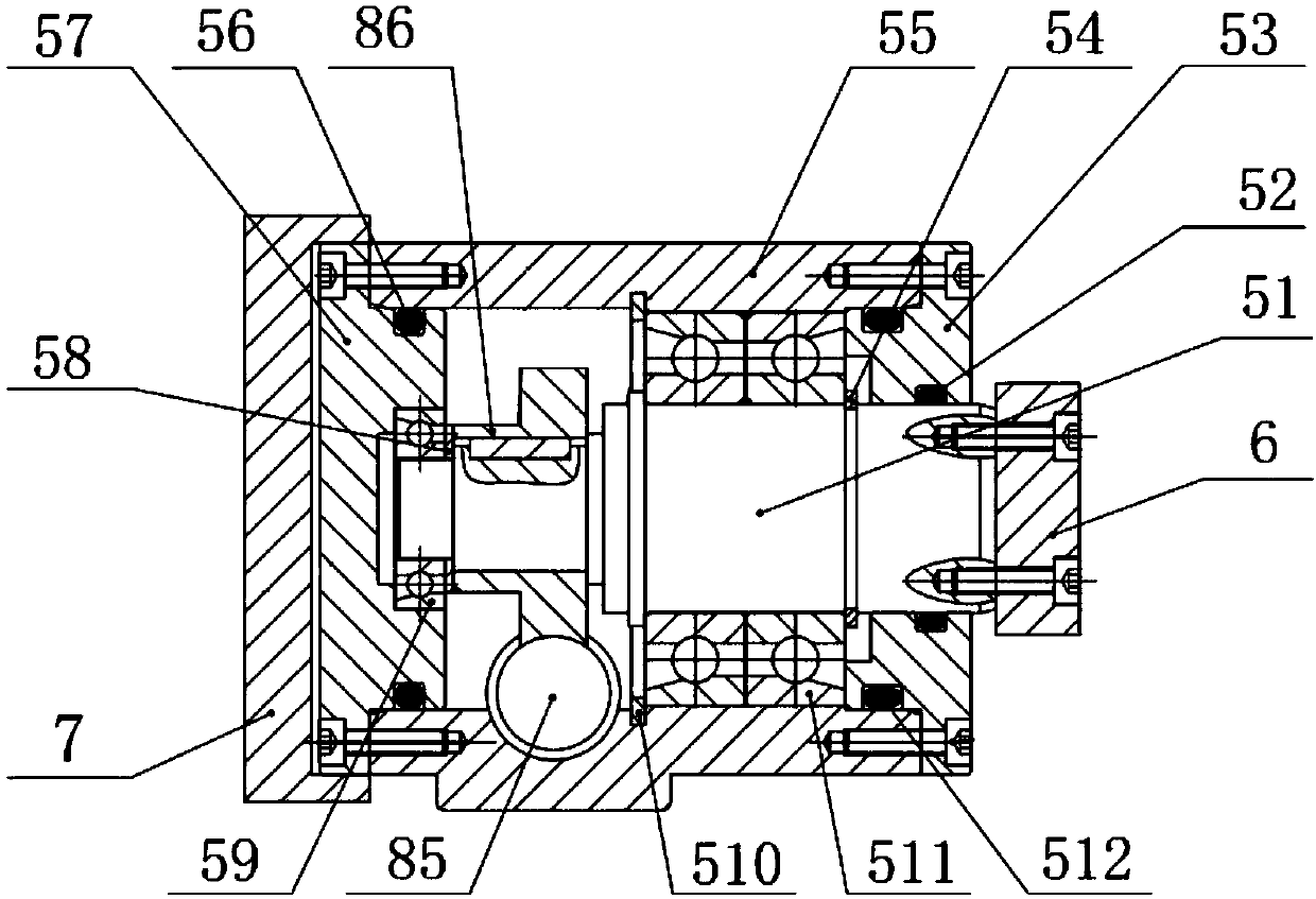
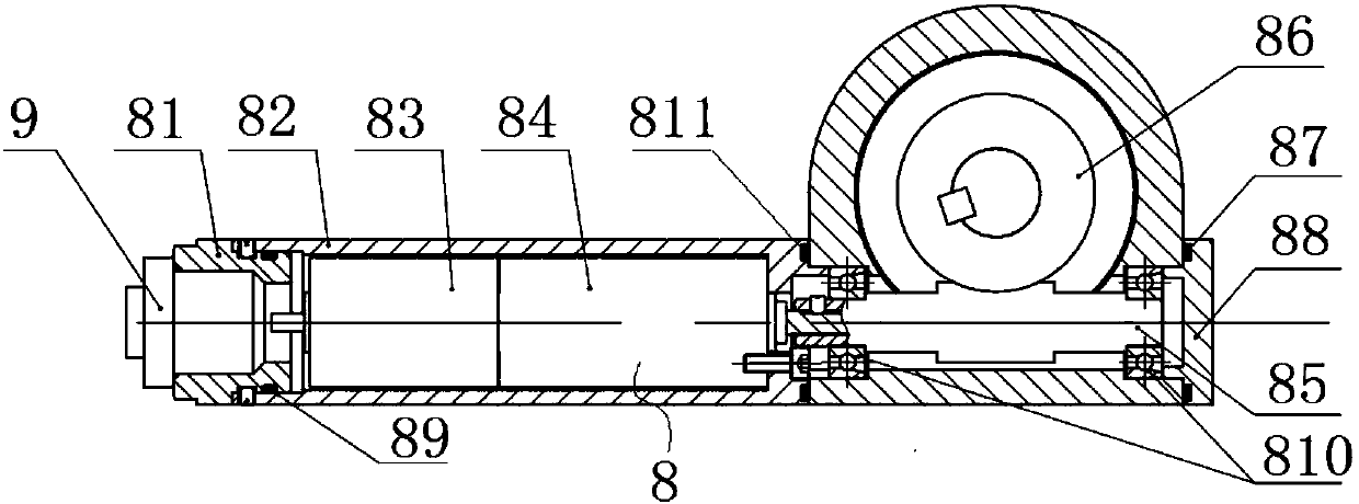
  • Underwater self-folding antenna

Examples


Embodiment Construction

[0023] The present invention will be described in further detail below in conjunction with the accompanying drawings.

[0024] Such as Figure 1~3 As shown, the present invention includes an antenna assembly, an electronic cabin 4, a base 5, a driving mechanism 8 and a base 10, the base 5 and the driving mechanism 8 are all arranged on the base 10, and the base 5 is provided with There is a rotating shaft 51, and the rotating shaft 51 is driven to rotate by the drive mechanism 8, the electronic cabin 4 is connected to the base 5, and the electronic cabin 4 is driven to swing by the rotating shaft 51, the antenna assembly Installed at the end of the electronic cabin 4 away from the base 10, such as figure 1 As shown, the antenna assembly includes an iridium satellite antenna 1 , a radio antenna 2 and a strobe light 3 .

[0025] Such as Figure 2~3 As shown, the driving mechanism 8 includes a driving device, a worm 85 and a worm wheel 86, wherein the worm 85 is driven to rota...


PUM


Abstract

The invention relates to the technical field of underwater vehicle communication and particularly relates to an underwater self-folding antenna comprising an antenna assembly, an electronic cabin, a base, a driving mechanism and a bottom seat. The base and the driving mechanism are all arranged on the bottom seat, a rotating shaft is arranged in the base, the rotating shaft is driven to rotate bythe driving mechanism, the electronic cabin is connected to the base, the electronic cabin is driven to swing by the rotating shaft, the antenna assembly is mounted at an end of the electronic cabin away from the bottom seat, an electronic pressure switch is arranged on the electronic cabin, and the driving mechanism controls start and stop by the electronic pressure switch. When the underwater self-folding antenna does not need to communicate, the antenna assembly is laid down inside an aircraft, the antenna assembly is erected when the communication is needed, the navigation resistance of the underwater vehicle is effectively reduced, the antenna assembly is avoided from being hit, and unnecessary energy loss is reduced.

Description

technical field [0001] The invention relates to the technical field of underwater vehicle communication, in particular to an underwater autonomous folding antenna. Background technique [0002] Iridium antennas, radio antennas, and strobe lights are important components of autonomous underwater vehicles, and are crucial for vehicle position indication, surface communication, and recovery. If the iridium antenna, radio antenna, and strobe light are placed inside the aircraft, it will affect the signal reception strength or even fail. For example, the wind and waves at sea are strong, the aircraft fluctuates violently on the water surface, and the antenna is submerged in the water surface, etc. will cause signal reception failure. , so the iridium satellite antenna etc. are all installed outside the underwater vehicle in the prior art, and have a certain height. But on the other hand, when the antenna is fixed on the outside of the aircraft alone, the aircraft will generate g...

Claims


Application Information

Patent Timeline
IPC IPC(8): H01Q1/04H01Q1/08
CPCH01Q1/04H01Q1/08
Inventor 赵红印尹远王福利徐会希徐春晖
Owner SHENYANG INST OF AUTOMATION - CHINESE ACAD OF SCI
Learn More