
Control circuit and control method of flyback converter

A kind of flyback converter, control circuit technology

Active Publication Date: 2020-08-04
DELTA ELECTRONICS (SHANGHAI) CO LTD
View PDF4 Cites 0 Cited by
  • Summary
  • Abstract
  • Description
  • Claims
  • Application Information

AI Technical Summary

Problems solved by technology

[0007] Embodiments of the present invention provide a control circuit and control method of a flyback converter to solve the problem that the control circuit of the flyback converter in the prior art has an error in sampling the current, resulting in that the control accuracy of the output current cannot meet the requirements. Technical issues required for practical application

Method used


Image

  • Control circuit and control method of flyback converter
  • Control circuit and control method of flyback converter
  • Control circuit and control method of flyback converter

Examples


Embodiment Construction

[0102] In order to make the purpose, technical solutions and advantages of the embodiments of the present invention clearer, the technical solutions in the embodiments of the present invention will be clearly and completely described below in conjunction with the drawings in the embodiments of the present invention. Obviously, the described embodiments It is a part of embodiments of the present invention, but not all embodiments. Based on the embodiments of the present invention, all other embodiments obtained by persons of ordinary skill in the art without creative efforts fall within the protection scope of the present invention.

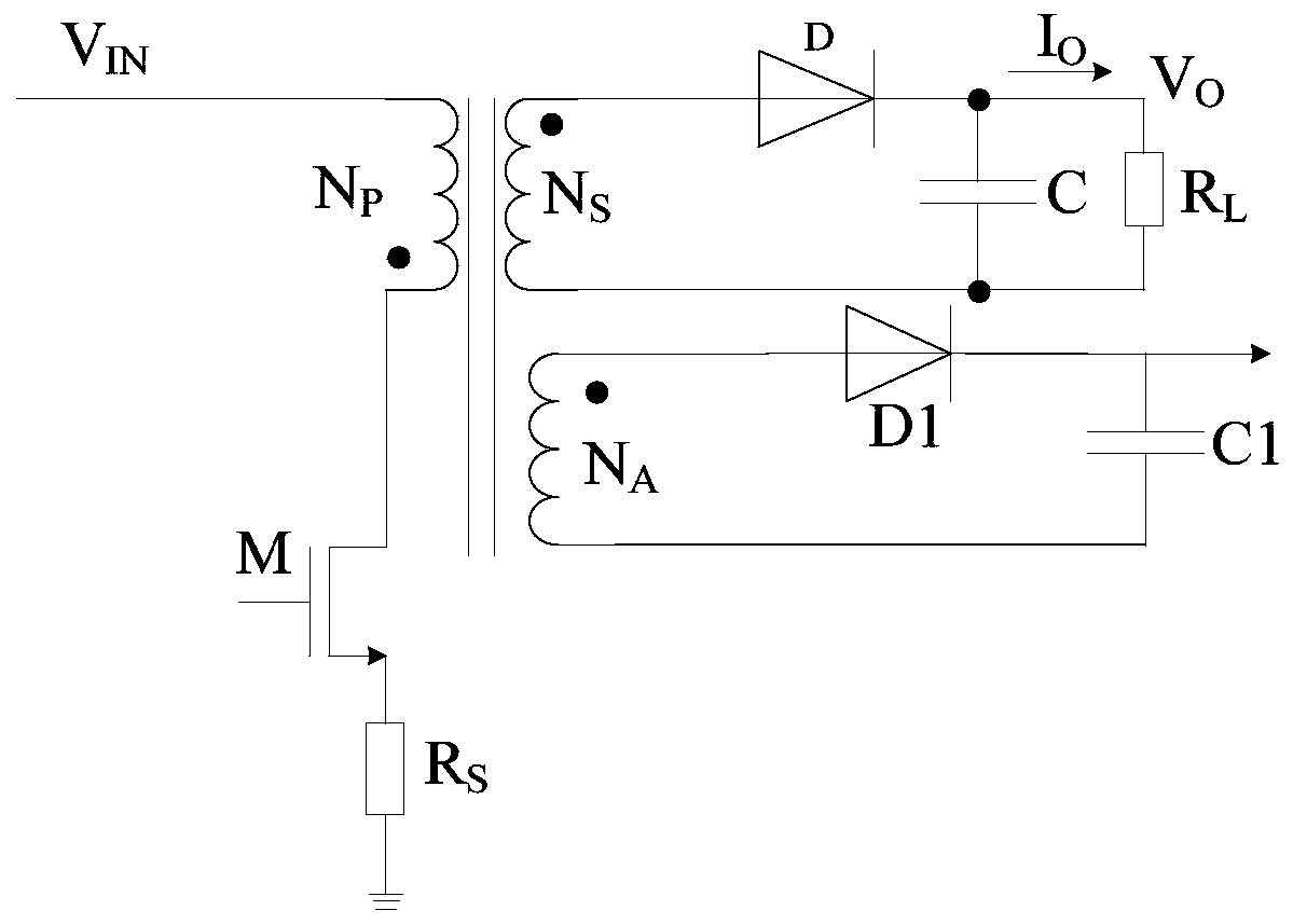
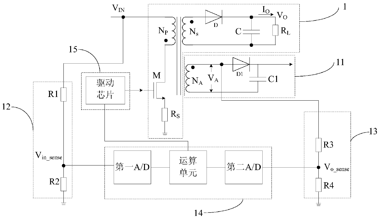
[0103] In order to solve the problem in the prior art that the control circuit of the flyback converter has an error in the sampling of the current, resulting in that the control accuracy of the output current cannot meet the needs of practical applications, an embodiment of the present invention provides a flyback converter control circuit.

[0...


PUM


Abstract

Embodiments of the present invention provide a control circuit and a control method of a flyback converter, the control circuit includes: a first sampling module, a second sampling module, and a control module; the first sampling module is connected to the control module and the flyback converter respectively coupled to the controller, and output a first voltage signal to the control module; the second sampling module is respectively coupled to the control module and the flyback converter, and outputs a second voltage signal to the control module; wherein, the first voltage signal reflects The input voltage of the flyback converter, the second voltage signal reflects the output voltage of the flyback converter; the control module outputs a control signal according to the first voltage signal and the second voltage signal, and the control signal reflects the switch in the flyback converter tube conduction time. The embodiment of the present invention can improve the control precision of the output current.

Description

technical field [0001] The embodiments of the present invention relate to the field of electric power technology, and in particular to a control circuit and a control method of a flyback converter. Background technique [0002] Currently, flyback converters, especially isolated flyback converters, are widely used in the field of dimming. [0003] Picture 1-1 It is a topology diagram of an isolated flyback converter and primary side auxiliary circuit. Among them, the flyback converter may include a primary winding, a secondary winding, a secondary diode D, a capacitor C, and a resistor R L , switch tube M and resistor R s , where the input voltage Vin is applied between the input terminal of the flyback converter and the ground terminal of the primary side, and by controlling the conduction time of the switch tube M, the final output voltage Vo is at both ends of the load, for example Picture 1-1 The load resistor R in L . Specifically, such as Picture 1-1 As shown, th...

Claims


Application Information

Patent Timeline
Patent Type & Authority Patents(China)
IPC IPC(8): H02M3/335
CPCH02M3/33515H02M3/33523H02M1/0009H02M1/08H03M1/1245
Inventor 傅小平章兴华
Owner DELTA ELECTRONICS (SHANGHAI) CO LTD
Learn More