
Eye vision measuring apparatus

A measuring device and vision technology, which is applied in the fields of eye testing equipment, medical science, diagnosis, etc., can solve the problems of difficult device body regulation, difficult eye chart, insufficient environmental protection and energy saving design, etc., and achieves the effect of convenient adjustment and use

Active Publication Date: 2019-03-29
连云港市一明医疗科技有限公司
View PDF6 Cites 3 Cited by
  • Summary
  • Abstract
  • Description
  • Claims
  • Application Information

AI Technical Summary

Problems solved by technology

[0004] The object of the present invention is to provide a kind of eyesight measuring device, to solve a kind of vision detecting device disclosed in Chinese invention patent application publication specification CN 106821298 A proposed in the above-mentioned background technology, this vision detecting device, although, can pass a The driving source can realize the adjustment of the same group of visual targets, which can improve the adjustment efficiency and reduce the manufacturing cost, but the design of the device is not environmentally friendly and energy-saving. Inherent there is the problem that it is difficult to conveniently regulate the movement and stability of the device body. At the same time, due to the different lengths of different eye charts, it is difficult for the general device to properly and dexterously clamp the eye chart, and the general device It is also difficult to use eye charts and other vision measurement tools in combination

Method used


Image

  • Eye vision measuring apparatus
  • Eye vision measuring apparatus
  • Eye vision measuring apparatus

Examples


Embodiment Construction

[0026] The following will clearly and completely describe the technical solutions in the embodiments of the present invention with reference to the accompanying drawings in the embodiments of the present invention. Obviously, the described embodiments are only some, not all, embodiments of the present invention.

[0027] In the description of the present invention, unless otherwise stated, the meaning of "plurality" is two or more; the terms "upper", "lower", "left", "right", "inner", "outer" , "front end", "rear end", "head", "tail", etc. indicate the orientation or positional relationship based on the orientation or positional relationship shown in the drawings, and are only for the convenience of describing the present invention and simplifying the description, rather than Nothing indicating or implying that a referenced device or element must have a particular orientation, be constructed, and operate in a particular orientation should therefore not be construed as limiting ...


PUM


Abstract

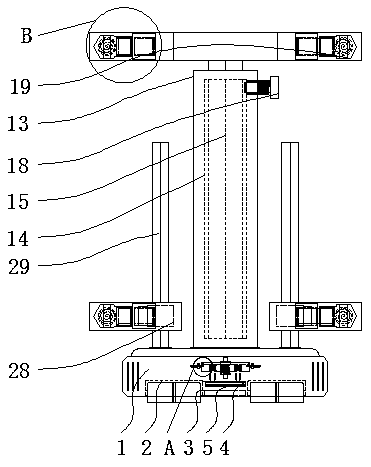
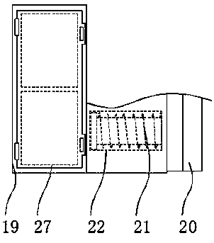
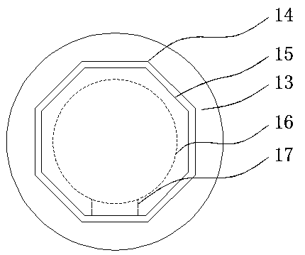
The invention relates to an eye vision measuring apparatus. The eye vision measuring apparatus comprises a base and a storage slot; internal through grooves are arranged inside both the left end and the right end of the bottom of the base; a transmission rotor is arranged at the middle of a bottom end of the base; an inner groove is arranged outside the transmission rotor; a top end of the inner groove is connected with a limit plate; a top end at the middle of the base is connected with a central column strip; a slot is arranged inside the central column strip; a slot post is arranged at an inner end of the slot; a central storage piece is arranged at the middle of the slot post; and a feeding port is connected with the outer side of a top end of the central storage piece. The eye visionmeasuring apparatus has the following beneficial effects: by arranging the storage slot, a connecting piece and a spring column, the eye vision measuring apparatus is capable of connecting and placingthe connecting piece through the storage slot with large caliber; cooperated use of the connecting piece with side connecting bolts is facilitated by curved structures at both the left end and the right end of the connecting piece; and the connecting piece is pushed downward under elastic force of the spring column, so that, descending of the limit plate is facilitated so as to carry out brake operation.

Description

technical field [0001] The invention relates to the technical field of vision measurement, in particular to an eye vision measurement device. Background technique [0002] Vision refers to the ability of the retina to distinguish images. The quality of vision is judged by the ability of the retina to distinguish images. However, when the refractive media of the eye (such as cornea, lens, vitreous body, etc.) , farsightedness, astigmatism, etc.), even if the retinal function is good, the visual acuity will still decline, and the refractive medium of the eye is cloudy, which can be treated with surgery, while the refractive error needs to be corrected with lenses. [0003] A vision detection device disclosed in the Chinese Invention Patent Application Publication Specification CN 106821298 A, although the vision detection device can realize the adjustment of the same group of visual targets through a driving source, which can improve the adjustment efficiency and reduce the ma...

Claims


Application Information

Patent Timeline
IPC IPC(8): A61B3/032
CPCA61B3/032
Inventor 汪云凤
Owner 连云港市一明医疗科技有限公司
Learn More