Cycle stirring reactor for chemical product manufacturing

A technology of circulating stirring and chemical products, applied in chemical/physical/physical chemical fixed reactors, chemical instruments and methods, chemical/physical processes, etc., can solve problems such as accelerating reaction rate and stratification, and achieve accelerated reaction rate , prevent the precipitation of unity, and fully respond to the effect

Inactive Publication Date: 2019-03-29
孙洁
View PDF7 Cites 6 Cited by
  • Summary
  • Abstract
  • Description
  • Claims
  • Application Information

AI Technical Summary

Problems solved by technology

[0003] At present, most of the existing reactors are equipped with a stirring structure inside, and the internal reactants are fully mixed and contacted by stirring to realize the effect of speeding up the reaction rate. However, the reactors commonly used in the market and factories do not have the function of recycling. When in use, the upper part of the mixture is mostly lighter substances, and the bottom is precipitated by heavier substances, so there will be stratification

Method used


Image

  • Cycle stirring reactor for chemical product manufacturing
  • Cycle stirring reactor for chemical product manufacturing
  • Cycle stirring reactor for chemical product manufacturing

Examples


Embodiment 1

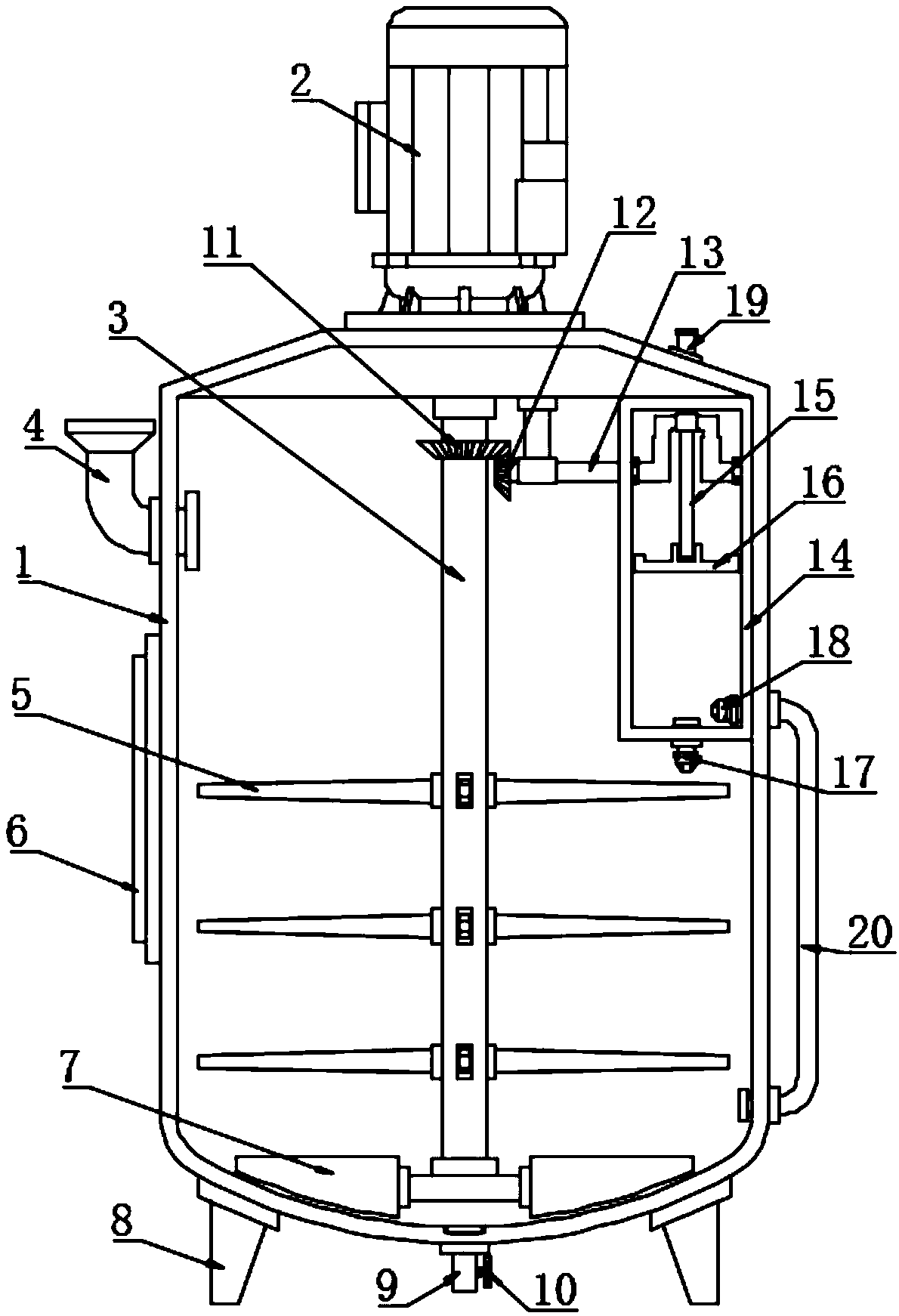
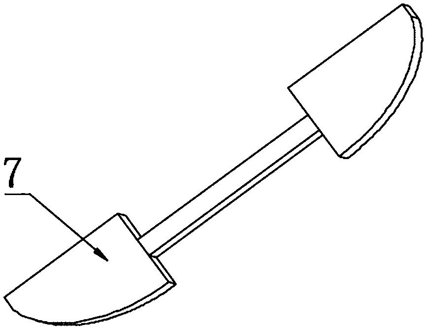
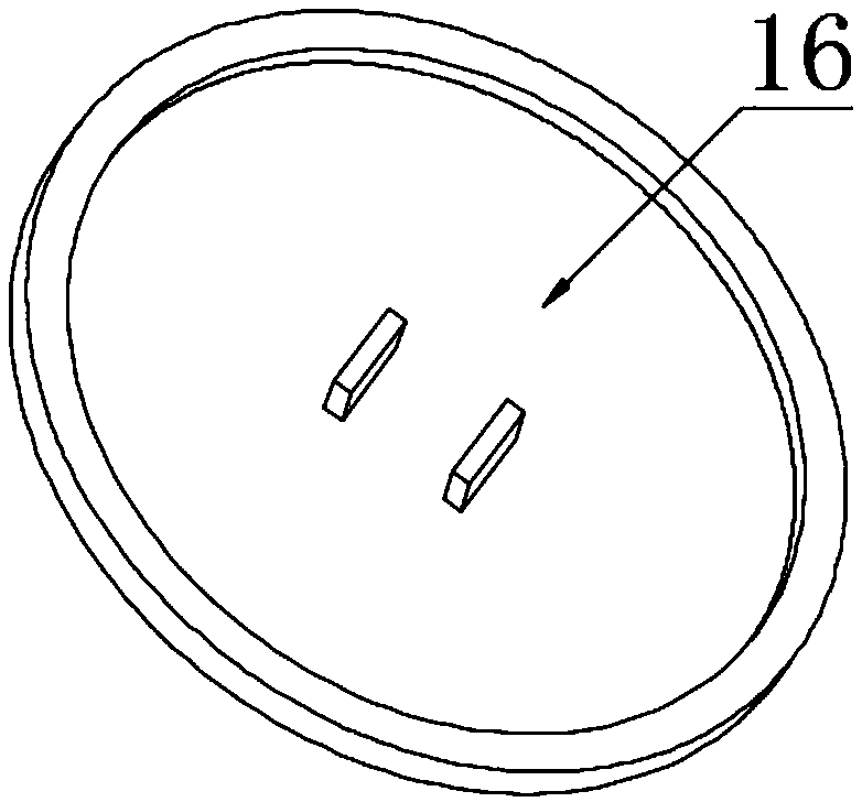
[0020] see Figure 1~3 , in the embodiment of the present invention, a kind of circulating stirring reactor for chemical product manufacturing, comprises reactor housing 1, driving motor 3, scraper 7, discharge pipe 9, circulation chamber 14 and return pipe 20; Said reactor housing The upper end of 1 is fixedly installed on the drive motor 2. Specifically, the lower part of the drive motor 2 is fixedly connected to the upper end of the reactor shell 1 through flange bolts, the lower part of the drive motor 2 is connected to the stirring shaft 3 by rotation, and the lead wire of the drive motor 2 is connected to the power supply and the switch. The actuating switch makes the drive motor 2 energized to drive the stirring shaft 3 to rotate; A scraper 7 is fixedly connected, wherein, the bottom of the scraper 7 has the same profile as the bottom of the reactor shell 1, and a control panel 6 is fixed on the side wall of the reactor shell 1, and the signal of the control panel 6 is ...

Embodiment 2

[0023] In order to make the technical solutions in this application more detailed and complete, now some supplements and explanations are made on the basis of the above-mentioned embodiment 1, so that the disclosure of the technical means adopted in this application is more sufficient, specifically, the supplements and explanations Part of the technical feature is that the control panel 6 has a central processing unit, a display screen and a control area, wherein the display screen signal is connected to the central processing unit and the drive motor 2, and the control area is provided with indicator lights and switch buttons, switch buttons and indications. The lamps are electrically connected to the power supply and the central processing unit respectively, and are operated through the display screen in the control panel 6 and transmitted to the central processing unit, so that the operation command is changed into a digital signal and sent to the drive motor 2 to realize the...


PUM


Abstract

The invention discloses a cycle stirring reactor for chemical product manufacturing. A driving motor is fixedly mounted at the upper end of a reactor shell, the lower part of the driving motor is fixedly connected with the upper end of the reactor shell through a flange and bolts, the lower part of the driving motor is rotationally connected with a stirring shaft, and the driving motor is connected with a power supply and a switch through a lead wire; the stirring shaft is longitudinally equidistantly provided with a plurality of stirring blades, the stirring blades are circumferentially distributed on the stirring shaft, and two sides of the lower end of the stirring shaft are fixedly connected with scraping plates, and the lower parts of the scraping plates have the same counter with thereactor shell; and the sidewall of the reactor shell is fixedly provided with a control panel, the control panel is in signal connection with the driving motor, and the control panel is a touch panel. The driving motor drives the stirring shaft to rotate in order to drive the stirring blades and the scraping plates to rotate, the rotating stirring blades sufficiently mix materials in the reactorto improve the reaction rate, and the scraping plates can effectively prevent the materials from aggregating and precipitating to the bottom of the reactor.

Description

technical field [0001] The invention relates to chemical equipment, in particular to a circulating stirring reaction kettle for chemical product manufacturing. Background technique [0002] The reactor is a comprehensive reaction vessel, and the structure, function and configuration accessories of the reactor are designed according to the reaction conditions. From the beginning of the feed-reaction-discharge, the preset reaction steps can be completed with a high degree of automation, and the temperature, pressure, mechanical control (stirring, blasting, etc.), reactants / products during the reaction process Important parameters such as concentration are strictly regulated. [0003] At present, most of the existing reactors are equipped with a stirring structure inside, and the internal reactants are fully mixed and contacted by stirring to realize the effect of speeding up the reaction rate. However, the reactors commonly used in the market and factories do not have the fun...

Claims


Application Information

Patent Timeline
Patent Type & Authority Applications(China)
IPC IPC(8): B01J19/18
CPCB01J19/0066B01J19/1875
Inventor 孙洁
Owner 孙洁
Why Eureka
Try Eureka