
Furnace slag separating equipment

A technology for separating equipment and slag, which is applied in the direction of solid separation, filter screen, grid, etc., can solve the problems of unfavorable use, old equipment, large loss, etc., and achieve the effect of reducing costs and improving work efficiency

Pending Publication Date: 2019-03-29
JIANGDU SHUNDA MACHINERY
View PDF0 Cites 0 Cited by
  • Summary
  • Abstract
  • Description
  • Claims
  • Application Information

AI Technical Summary

Problems solved by technology

[0002] Blast furnace slag is a solid waste formed from gangue in ore, ash in fuel and solvent, generally non-volatile components in limestone during the blast furnace ironmaking process; it mainly contains calcium, silicon, aluminum, magnesium and iron. Oxides and a small amount of sulfide; Blast furnace slag is an industrial solid waste. The slag discharged from the blast furnace ironmaking process is also called blast furnace slag, which can be divided into steelmaking pig iron slag, casting pig iron slag, ferromanganese slag, etc.; Slag with different diameters has different uses; slag with small particles can be used as a new material for walls, while slag with large particles can only be used for brick making, etc. The traditional equipment is relatively old, and the energy consumption is high and the loss is large ;Larger floor space, not conducive to long-term use

Method used


Image

  • Furnace slag separating equipment
  • Furnace slag separating equipment

Examples


Embodiment Construction

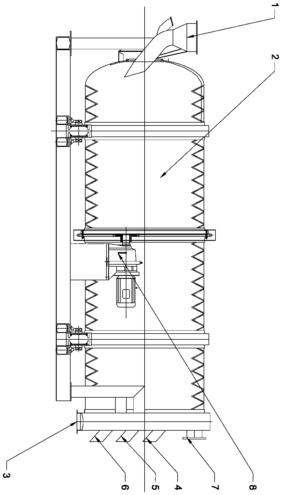
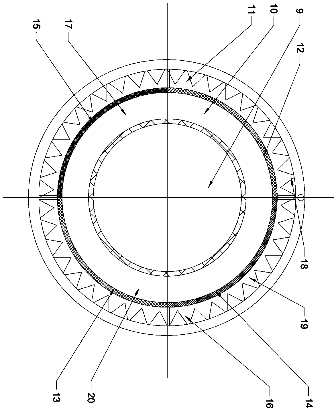
[0019] The object of the present invention is achieved in the following way: a slag separation equipment, comprising a main support frame, one side of the main support frame is equipped with a secondary support clip, the main support frame is equipped with a drum 2, and the auxiliary support A driving device 8 is provided on the supporting frame, a rotating assembly is provided on the outer periphery of the drum 2, and the driving device 8 is directly connected with the rotating assembly, an outlet is provided on one side of the drum 2, and an outlet is provided on the other side of the drum 2. There is an inlet 1; the drum 2 is provided with several layers of filter layers, and the drum 2 is also provided with a spray device 21, and the drum 2 is provided with a water inlet 7 in conjunction with the spray device 21, and the drum 2 is equipped with The water inlet 7 is provided with a water outlet 3; several layers of filter layers are correspondingly provided with respective o...


PUM


Abstract

The invention relates to furnace slag separating equipment in the field of metallurgy environmental protection. The furnace slag separating equipment comprises a main supporting frame. An auxiliary supporting frame is arranged on one side of the main supporting frame in a cooperating manner. A roller is arranged on the main supporting frame in a cooperating manner. A drive device is arranged on the auxiliary supporting frame in a cooperating manner. The furnace slag separating equipment is characterized in that a rotating assembly is arranged on the periphery of the roller; the drive device isdirectly connected with the rolling assembly; an outlet is formed in one side of the roller, and an inlet is formed in the other side of the roller; multiple filter layers are arranged in the roller;a spraying device is further arranged in the roller in a cooperating manner; a water inlet is formed in the roller in a manner of cooperating with the spraying device; a water outlet is formed in theroller in a manner of cooperating with the water inlet; and the multiple filter layers are correspondingly provided with outlets. By means of the furnace slag separating equipment, furnace slag is subjected to multi-stage separating through the multiple sets of filter layers, the process that traditional equipment needs multiple steps is avoided, the work efficiency is improved, and the cost is reduced.

Description

technical field [0001] The invention relates to a slag separation device in the field of metallurgy and environmental protection. Background technique [0002] Blast furnace slag is a solid waste formed from gangue in ore, ash in fuel and solvent, generally non-volatile components in limestone during the blast furnace ironmaking process; it mainly contains calcium, silicon, aluminum, magnesium and iron. Oxides and a small amount of sulfide; Blast furnace slag is an industrial solid waste. The slag discharged from the blast furnace ironmaking process is also called blast furnace slag, which can be divided into steelmaking pig iron slag, casting pig iron slag, ferromanganese slag, etc.; Slag with different diameters has different uses; slag with small particles can be used as a new material for walls, while slag with large particles can only be used for brick making, etc. The traditional equipment is relatively old, and the energy consumption is high and the loss is large ; I...

Claims


Application Information

Patent Timeline
Patent Type & Authority Applications(China)
IPC IPC(8): B07B1/22B07B1/42B07B1/46C22B7/04
CPCC22B7/04B07B1/22B07B1/42B07B1/46B07B2201/04Y02P10/20
Inventor 潘志刚
Owner JIANGDU SHUNDA MACHINERY
Learn More