Kitchen waste disposer and kitchen waste treatment method thereof

A kitchen waste and processing method technology, applied in the field of machinery, can solve the problems of falling into the interior of the kitchen waste disposer, soiling the kitchen waste disposer, and the inability of all residues to fall into it, so as to achieve accurate blanking and ensure Accuracy, the effect of avoiding positioning errors

Active Publication Date: 2019-03-29
徐州川珉建设工程有限公司
View PDF6 Cites 2 Cited by
  • Summary
  • Abstract
  • Description
  • Claims
  • Application Information

AI Technical Summary

Problems solved by technology

Therefore, the drying chamber is a semi-closed structure with one end open. In order to ensure that the debris can just fall into the drying chamber, it must be ensured that the drying chamber is just below the discharge channel of the crushed residue after rotation. If the drying chamber is inclined, It will cause part of the residue to fall into the drying room, and even fall into the inside of the kitchen waste disposer, which will make the kitchen waste disposer dirty. In this way, it needs to be cleaned frequently, which is very troublesome. , if the drying chamber is tilted, the dried residue cannot fall into the collection device completely, resulting in part of the residue being re-dried, and the efficiency is very low

Method used


Image

  • Kitchen waste disposer and kitchen waste treatment method thereof
  • Kitchen waste disposer and kitchen waste treatment method thereof
  • Kitchen waste disposer and kitchen waste treatment method thereof

Examples


Embodiment Construction

[0019] The following will clearly and completely describe the technical solutions in the embodiments of the present invention with reference to the accompanying drawings in the embodiments of the present invention. Obviously, the described embodiments are only some, not all, embodiments of the present invention.

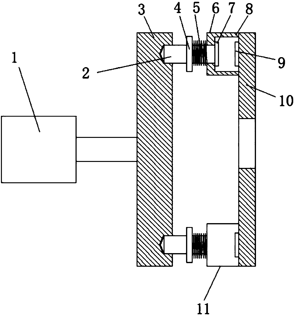
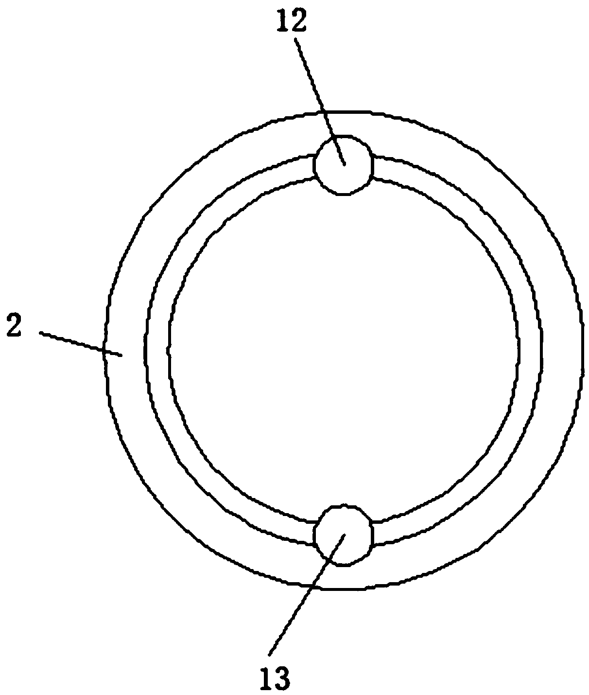
[0020] refer to Figure 1-3 , a motor rotation positioning structure, including a motor 1, a turntable 3, a first limit device 6, a second limit device 11 and a fixed plate 10, the end of the output shaft of the motor 1 is equipped with a turntable 3, and the output of the motor 1 The shaft is perpendicular to the surface of the turntable 3, and the side of the turntable 3 away from the motor is provided with an annular chute, and the cross section of the chute is tapered, and the bottom of the chute is provided with a symmetrical first positioning hole 12 and a second positioning hole 13. The side of the turntable 3 away from the motor is provided with a fixed plate...


PUM


Abstract

The invention discloses a kitchen waste disposer and a kitchen waste treatment method thereof. The kitchen waste disposer comprises a motor, a rotating disc, a first limiting device, a second limitingdevice and a fixing plate, wherein the rotating disc is arranged at the tail end of an output shaft of the motor, the output shaft of the motor is perpendicular to the surface of the rotating disc, an annular sliding groove is formed in the side edge, away from the motor, of the rotating disc, the cross section of the sliding groove is conical, a first positioning hole and a second positioning hole which are symmetrical are formed in the bottom of the sliding groove, the side, far away from the motor, of the rotating disc is provided with the fixing plate, the side edge, close to the rotatingdisc, of the fixing plate is provided with the first limiting device and the second limiting device, the first limiting device comprises a positioning pin, a shaft shoulder, a spring, a first electromagnetic disc, a base and a second electromagnetic disc, wherein the base is of a hollow structure with one end open, one end of an upper opening of the base is installed on the fixing plate, and a guide through hole is formed in the side edge, away from the fixing plate, of the base. According to the kitchen waste disposer and the kitchen waste treatment method thereof, the accuracy of the rotating position of a drying chamber can be ensured, so that falling is accurate, pollution to a box body and repeated drying are avoided, and the efficiency is very high.

Description

technical field [0001] The invention relates to the field of mechanical technology, in particular to a kitchen waste disposer and a kitchen waste treatment method thereof. Background technique [0002] Existing kitchen waste disposers generally include a crushing device, an extruding device, a drying device and a collecting device. The crushing device uses knives to crush the kitchen waste to obtain water-containing fragments. The extrusion device squeezes the water-containing fragments. The oil and water enter the oil-water separator, and the residue falls into the drying chamber of the drying device. After drying, it is dried The device controls the rotation of the drying chamber so that the dried crushed material is poured into the collecting device, so that the crushed material can be packaged and placed for disposal. Therefore, the drying chamber is a semi-closed structure with one end open. In order to ensure that the debris can just fall into the drying chamber, it m...

Claims


Application Information

Patent Timeline
Patent Type & Authority Applications(China)
IPC IPC(8): B09B3/00F26B25/02
CPCF26B25/02E03C1/26B09B3/00
Inventor 不公告发明人
Owner 徐州川珉建设工程有限公司
Why Eureka
Try Eureka