Space-saving machining center with scrap iron pressing block function

A space-saving, machining center technology, applied in the direction of metal processing equipment, metal processing machinery parts, manufacturing tools, etc., can solve the problems of reducing the practicality and safety of machine tools, reducing work efficiency, low efficiency, etc., and achieves the reduction of blockage and discharge The effect of managing the probability of incidents, improving practicality and safety, and improving work efficiency

Inactive Publication Date: 2019-03-29
JIANGSU HUAXIA INTPROP SERVICE CO LTD
View PDF0 Cites 0 Cited by
  • Summary
  • Abstract
  • Description
  • Claims
  • Application Information

AI Technical Summary

Problems solved by technology

[0002] When the machining center is working, a large amount of iron filings will accumulate at the bottom of the machine tool. Usually, the processing of iron filings is to stop the machine tool and clean the iron filings to the discharge port by broom and other tools. This is very troublesome and inefficient. , once the operation is negligent, it is easy to be cut by the blade of the machine tool, which is very dangerous. Although there are some machine tools that automatically transfer iron filings, there are still many shortcomings in this kind of machine tool that transfers iron filings. It is very tiring to dump the iron filings back and forth, and the long strips of iron filings are often entangled in the outlet during the conveying process. In the material pipe, the iron filings are blocked, which affects the work and reduces the work efficiency. If these problems are not solved, the practicability and safety of the machine tool will be greatly reduced.

Method used


Image

  • Space-saving machining center with scrap iron pressing block function
  • Space-saving machining center with scrap iron pressing block function
  • Space-saving machining center with scrap iron pressing block function

Examples


Embodiment Construction

[0028] The present invention is described in further detail now in conjunction with accompanying drawing. These drawings are all simplified schematic diagrams, which only illustrate the basic structure of the present invention in a schematic manner, so they only show the configurations related to the present invention.

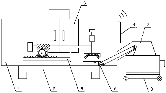
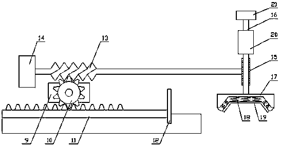
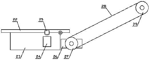
[0029] Such as Figure 1-Figure 4As shown, a space-saving machining center with the function of iron filings briquetting, including a main body 1, a base 2, a switch door 3, a central control mechanism 4, a processing mechanism, a pushing mechanism 5, a transmission mechanism 6, and a discharge pipe 7 and the collection box 8, the base 2 is arranged under the main body 1, the switch door 3 is arranged on the main body 1, the central control mechanism 4 is arranged on one side of the main body 1, the processing mechanism and the pushing mechanism 5 are all arranged inside the main body 1, the discharge pipe 7 is arranged on one side of the main body 1, the col...


PUM


Abstract

The invention relates to a space-saving machining center with a scrap iron pressing block function. The space-saving machining center with the scrap iron pressing block function comprises a main body,a base, an opening and closing door, a center control mechanism, a machining mechanism, a pushing and pressing mechanism, a transmission mechanism, a discharging pipe and a material collecting box. The pushing and pressing mechanism comprises a driving assembly, a pushing assembly and a pressing block assembly. The pushing assembly comprises a moving rod and a push plate; and the pressing block assembly comprises a worm, a second gear, a lifting rod, a first pressing plate, a spring and a second pressing plate. The transmission mechanism comprises an overturning assembly and a transmission assembly, the overturning assembly comprises a fixed plate, a bottom plate and a telescopic unit. According to the space-saving machining center with the scrap iron pressing block function, scrap iron in a machine tool can be cleaned and compressed through the pushing and pressing mechanism, and existing potential safety hazards during the scrap iron sweeping are avoided; and the probability of occurring the incident of the scrap iron enwinding and blocking the discharging pipe is reduced, the material collecting box can load more scrap iron at a time, and thus, the practicability and safety ofthe machine tool are improved.

Description

technical field [0001] The invention relates to the field of machining centers, in particular to a space-saving machining center with the function of briquetting iron chips. Background technique [0002] When the machining center is working, a large amount of iron filings will accumulate at the bottom of the machine tool. Usually, the processing of iron filings is to stop the machine tool and clean the iron filings to the discharge port by broom and other tools. This is very troublesome and inefficient. , once the operation is negligent, it is easy to be cut by the blade of the machine tool, which is very dangerous. Although there are some machine tools that automatically transfer iron filings, there are still many shortcomings in this kind of machine tool that transfers iron filings. It is very tiring to dump the iron filings back and forth, and the long strips of iron filings are often entangled in the outlet during the conveying process. In the material pipe, the iron fi...

Claims


Application Information

Patent Timeline
Patent Type & Authority Applications(China)
IPC IPC(8): B23Q11/00
CPCB23Q11/00B23Q11/0042
Inventor 张莹
Owner JIANGSU HUAXIA INTPROP SERVICE CO LTD
Why Eureka
Try Eureka