Spindle box of a precision numerical control machine tool

A technology of precision numerical control and spindle box, which is applied in the direction of metal processing machinery parts, metal processing equipment, maintenance and safety accessories, etc. It can solve the problems of inconvenient disassembly and assembly, troublesome maintenance of the spindle box, and not simple enough, so as to reduce external pipelines, Collection of convenient, easy-to-install effects

Active Publication Date: 2022-05-27
安徽新诺精工股份有限公司
View PDF0 Cites 0 Cited by
  • Summary
  • Abstract
  • Description
  • Claims
  • Application Information

AI Technical Summary

Problems solved by technology

[0003] Most of the existing spindle boxes are fixed on the base by bolts and nuts, which is not convenient enough to disassemble and assemble, which makes the maintenance of the spindle box more troublesome, and the coolant of the spindle box is transported through pipelines, which is not simple enough, and is prone to water leakage. Iron filings are not easy to collect, which makes it difficult to clean the machine tool

Method used


Image

  • Spindle box of a precision numerical control machine tool
  • Spindle box of a precision numerical control machine tool
  • Spindle box of a precision numerical control machine tool

Examples


Embodiment 1

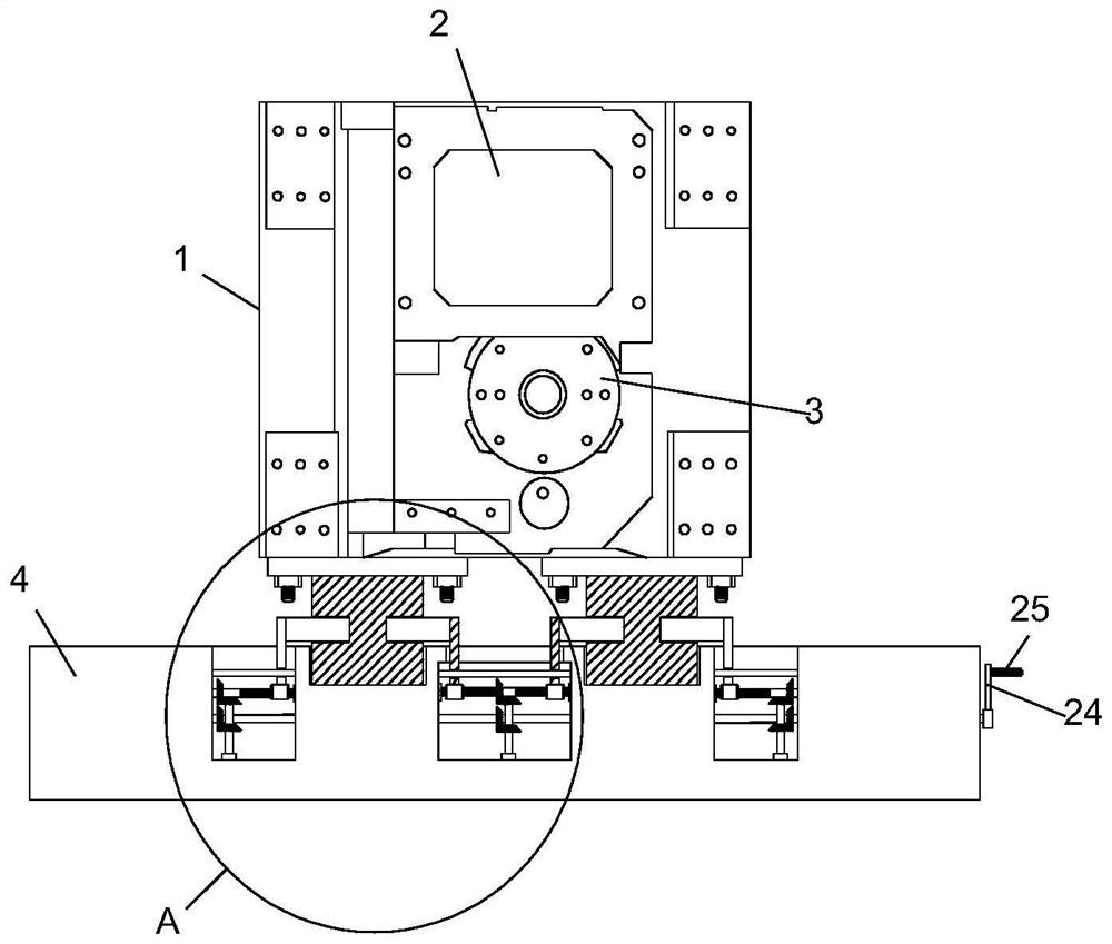
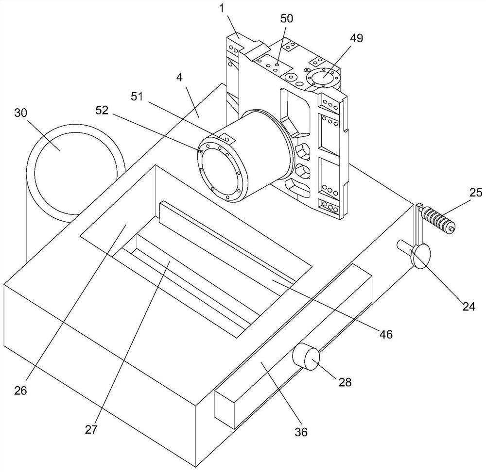
[0029] refer to Figure 1-6 , a spindle box of a precision CNC machine tool, including a spindle box body 1 and a base 4, the spindle box body 1 is detachably mounted on the top of the base 4, one side of the spindle box body 1 is provided with a motor mounting plate 2, and a motor mounting plate 2 It is used to install the spindle motor. One side of the spindle box body 1 is located below the motor mounting plate 2 with a knife-cutting cylinder mounting seat 3. The knife-cutting cylinder mounting seat 3 is used to fix the knife-cutting cylinder. Put it on the top of the spindle box body 1, and put the knife cylinder under the spindle box body 1, which changes the structure of the traditional spindle box and is more convenient for installation. The top of the spindle box body 1 is provided with a coolant inlet 50. The spindle box body 1. A spray ring 52 is installed on the side away from the motor mounting plate 2, and the spray ring 52 communicates with the cooling liquid inl...

Embodiment 2

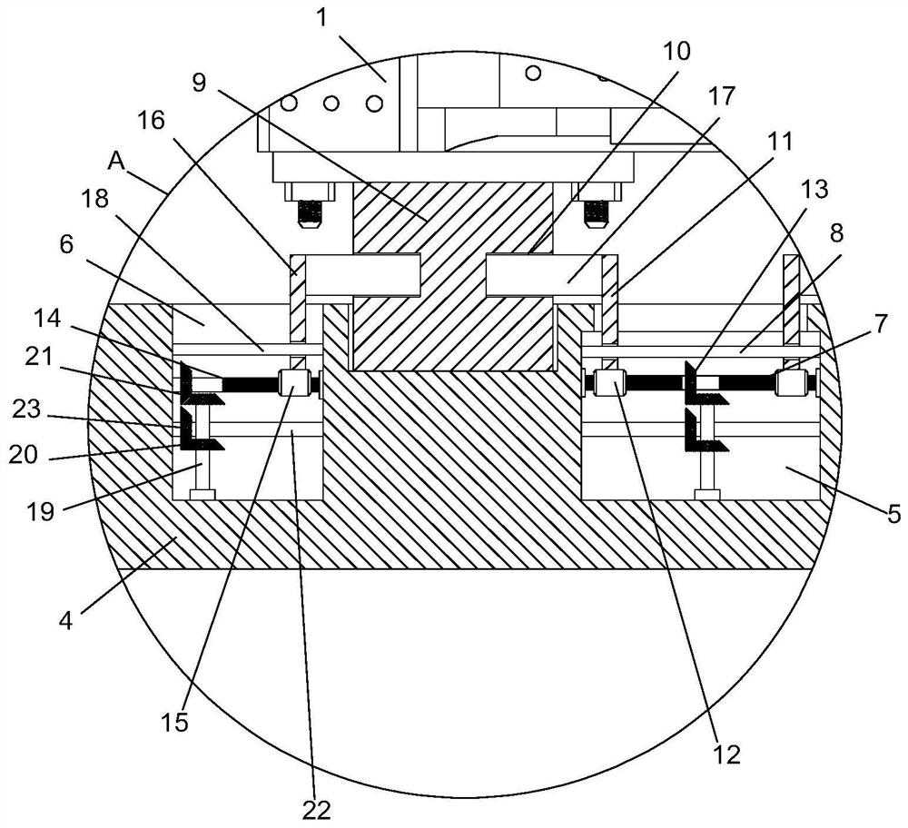
[0031] refer to Figure 1-6, The difference between this embodiment and Embodiment 1 is that both sides of the bottom end of the spindle box body 1 are fixedly connected with a positioning support block 9, and the top of the base 4 is provided with a positioning slot corresponding to the positioning support block 9. The positioning support block 9 extends into the positioning slot, the top of the base 4 is respectively provided with a first installation cavity 5 and a second installation cavity 6, the second installation cavity 6 is provided with two, and the two second installation cavities 6 are distributed with the first installation cavity 6. On both sides of the cavity 5, a two-way threaded rod 7 is rotatably installed between the inner walls of the two sides of the first installation cavity 5, and two first threaded sleeves 12 are installed on the outer threads of the two-way threaded rod 7. A first moving vertical plate 11 is fixedly connected to the top, and a first gu...

Embodiment 3

[0035] refer to Figure 1-6 The difference between this embodiment and Embodiment 1 is that the top end of the base 4 is provided with an iron filing groove 26, and the inner wall of the bottom end of the iron filing groove 26 is provided with a chip removal groove 27, and the width of the chip removal groove 27 is smaller than that of the iron filings. The width of the collection groove 26 and the larger diameter of the iron filing groove 26 can collect more iron filings and prevent the iron filings from scattering to the outside of the iron filing collection groove 26. A rotary motor 28 is fixedly installed on one side of the base 4, and rotates The output end of the motor 28 is fixedly connected with a conveying screw 29, the conveying screw 29 is located in the chip removal groove 27, and a storage cylinder 30 is fixedly connected to the side of the base 4 away from the rotating motor 28, and the storage cylinder 30 is communicated with the chip removal groove 27. A filter...


PUM


Abstract

The invention relates to the technical field of machine tools, and discloses a spindle box of a precision numerically controlled machine tool, which comprises a spindle box body and a base, the spindle box body is detachably mounted on the top of the base, and a motor mounting plate is arranged on one side of the spindle box body , one side of the spindle box body is located below the motor mounting plate with a knife cylinder mounting seat. The invention has ingenious structure, convenient use, convenient disassembly and assembly of the spindle box body, convenient maintenance of the spindle box, automatic collection of iron filings, and convenience for cleaning the iron filings. Above, put the cutting cylinder under the headstock body, which changes the structure of the traditional headstock and makes it easier to install. The coolant transmission channel and the spray ring are integrated inside the headstock body, which reduces the number of external pipes and avoids water leakage. The bed looks more concise, and adopts a closed spindle nut seat, which is more stable during processing and reduces vibration.

Description

technical field [0001] The invention relates to the technical field of machine tools, in particular to a spindle box of a precision numerically controlled machine tool. Background technique [0002] The headstock is an important part of the CNC machine tool and is used to arrange the working spindle of the machine tool, its transmission parts and the corresponding additional mechanisms. The spindle box is a complex transmission component, including spindle assembly, reversing mechanism, transmission mechanism, braking device, operating mechanism and lubricating device. Its main function is to support the main shaft and make it rotate, and realize the functions of main shaft starting, braking, shifting and reversing. [0003] Most of the existing spindle boxes are fixed on the base by bolts and nuts, and the disassembly and assembly are not convenient, which makes the maintenance of the spindle box more troublesome, and the cooling liquid of the spindle box is transported th...

Claims


Application Information

Patent Timeline
Patent Type & Authority Patents(China)
IPC IPC(8): B23B19/00B23Q11/00B23Q11/12
CPCB23Q1/70B23Q11/0042B23Q11/127
Inventor 赵祖喜吴晓东江昕谢振涛
Owner 安徽新诺精工股份有限公司
Why Eureka
Try Eureka