Spindle box of precise numerical control machine tool
A precision numerical control and spindle box technology, applied in the field of machine tools, can solve the problems of inconvenient disassembly and assembly, not simple enough, troublesome maintenance of the spindle box, etc., and achieve the effect of reducing external pipelines, reducing vibration and facilitating installation
- Summary
- Abstract
- Description
- Claims
- Application Information
AI Technical Summary
Problems solved by technology
Method used
Image
Examples
Embodiment 1
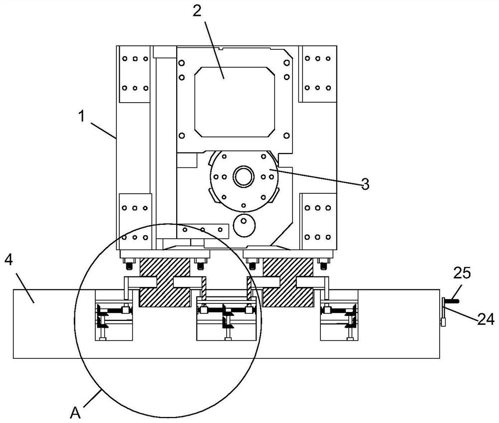
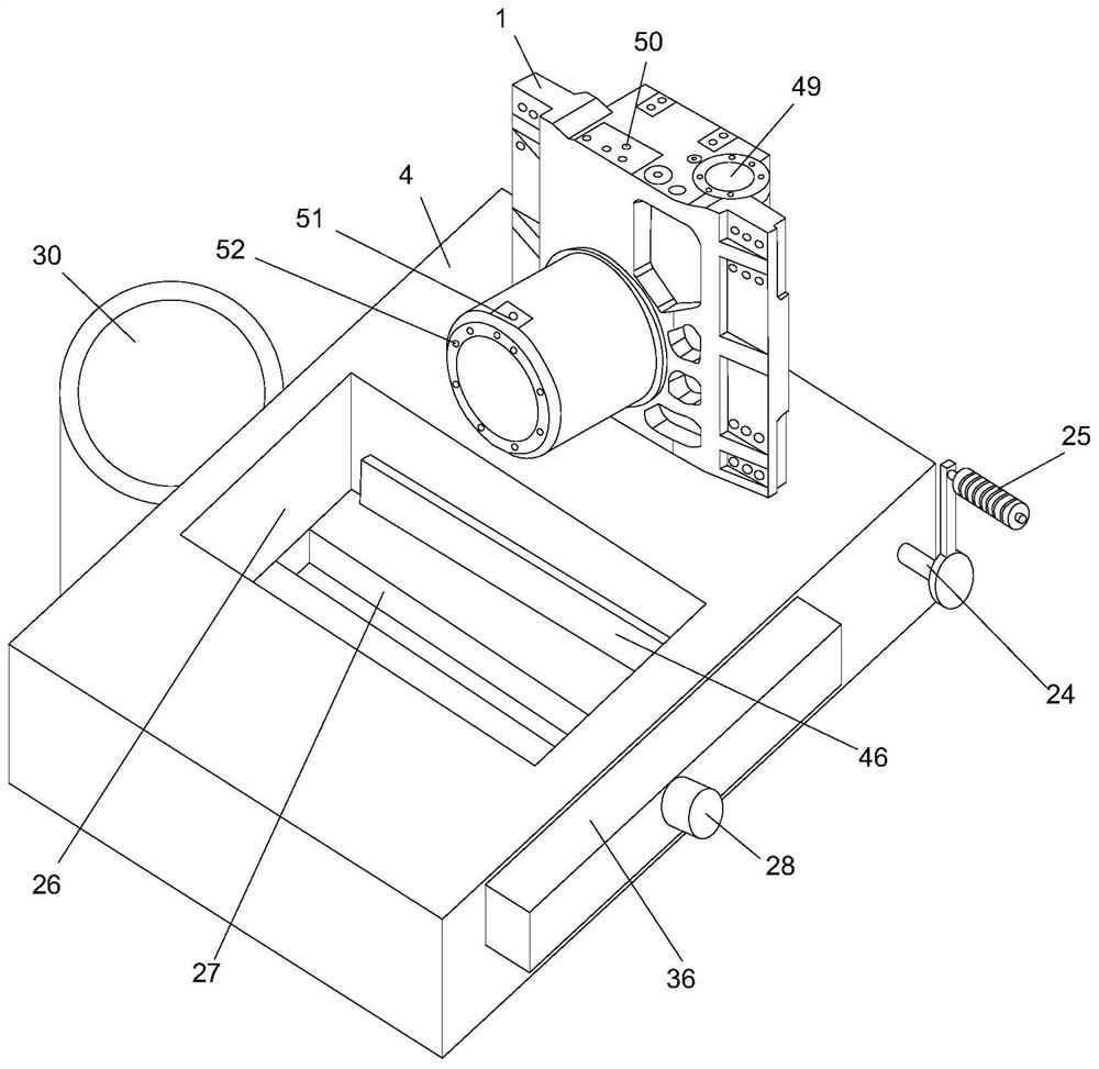
[0029] refer to Figure 1-6 , a spindle box of a precision numerical control machine tool, comprising a spindle box body 1 and a base 4, the spindle box body 1 is detachably mounted on the top of the base 4, one side of the spindle box body 1 is provided with a motor mounting plate 2, and a motor mounting plate 2 It is used to install the spindle motor. One side of the spindle box body 1 is located under the motor mounting plate 2. There is a knife cylinder mounting seat 3. The knife cylinder mounting seat 3 is used to fix the knife cylinder. With a new design, the spindle motor Put it on the top of the headstock body 1, and put the cutter cylinder under the headstock body 1, which changes the structure of the traditional headstock body and is easier to install. The top of the headstock body 1 is provided with a coolant inlet 50, and the headstock body 1 A spray ring 52 is installed on the side away from the motor mounting plate 2, and the spray ring 52 communicates with the c...
Embodiment 2
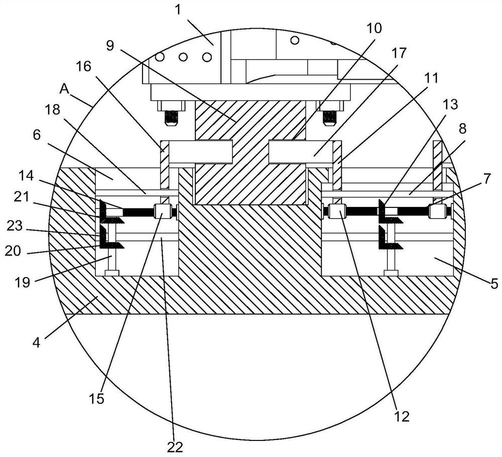
[0031] refer to Figure 1-6The difference between this embodiment and Embodiment 1 is that both sides of the bottom end of the spindle box body 1 are fixedly connected with positioning support blocks 9, and the top of the base 4 is provided with positioning slots corresponding to the positioning support blocks 9, and the positioning support blocks 9 extends into the positioning slot, the top of the base 4 is respectively provided with a first installation cavity 5 and a second installation cavity 6, two second installation cavities 6 are provided, and the two second installation cavities 6 are distributed with the first installation cavity On both sides of the chamber 5, two-way threaded rods 7 are installed in rotation between the inner walls on both sides of the first installation chamber 5, and two first threaded sleeves 12 are installed on the outer threads of the two-way threaded rods 7. The top end is fixedly connected with the first moving riser 11, and the first guide ...
Embodiment 3
[0035] refer to Figure 1-6 The difference between this embodiment and Embodiment 1 is that the top of the base 4 is provided with an iron filings collection groove 26, and the bottom inner wall of the iron filings collection groove 26 is provided with a chip removal groove 27, and the width of the chip removal groove 27 is smaller than that of the iron filings. The width of the collection tank 26, the larger diameter of the iron filings collection tank 26 can collect more iron filings, prevent the iron filings from scattering to the outside of the iron filings collection tank 26, and one side of the base 4 is fixedly equipped with a rotating motor 28, which rotates The output end of the motor 28 is fixedly connected with a conveying screw 29, the conveying screw 29 is located in the chip removal groove 27, the side of the base 4 away from the rotating motor 28 is fixedly connected with a storage cylinder 30, the storage cylinder 30 communicates with the chip removal groove 27,...
PUM
 Abstract
Description
Claims
Application Information
 - R&D
- Intellectual Property
- Life Sciences
- Materials
- Tech Scout
- Unparalleled Data Quality
- Higher Quality Content
- 60% Fewer Hallucinations
Browse by: Latest US Patents, China's latest patents, Technical Efficacy Thesaurus, Application Domain, Technology Topic, Popular Technical Reports.
© 2025 PatSnap. All rights reserved.Legal|Privacy policy|Modern Slavery Act Transparency Statement|Sitemap|About US| Contact US: help@patsnap.com


