
Wooden artware fixing clamp
A technology for fixing fixtures and handicrafts, which is applied in the direction of manufacturing tools, wood processing appliances, decorative arts, etc.
- Summary
- Abstract
- Description
- Claims
- Application Information
AI Technical Summary
Problems solved by technology
Method used
Image

Examples
Embodiment 1
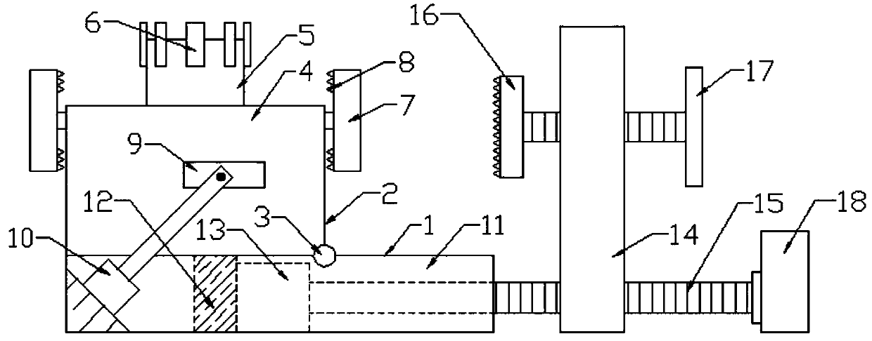
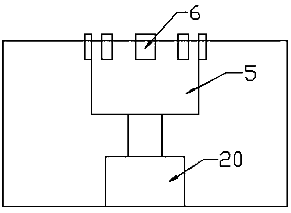
[0027] Such as figure 1 , Figure 3-4 and Figure 6 As shown, a wooden handicraft fixing fixture includes a fixing base 1 and a fixing table 2 arranged above the fixing base 1. There are several screw holes at equal distances on both sides of the fixing base 2, and all screw holes are threaded. A No. 2 locking button 7 is connected, and a No. 1 cavity 4 is provided inside the fixed table 2. A No. 2 cylinder 20 is installed in the No. 1 cavity 4. The end of the piston rod of the No. 2 cylinder 20 is fixed with a circular positioning seat 5 , The outer wall of the top end of the circular positioning seat 5 is equidistantly provided with several screw holes, and all screw holes are connected with a No. 1 lock button 6 by threads.
[0028] In this embodiment, a No. 1 cavity 4 is set in the fixed platform, and a circular positioning seat 5 is arranged in the No. 1 cavity 4, and then several No. 1 locking buttons 6 are connected on the outside of the circular positioning seat 5 ,...
Embodiment 2
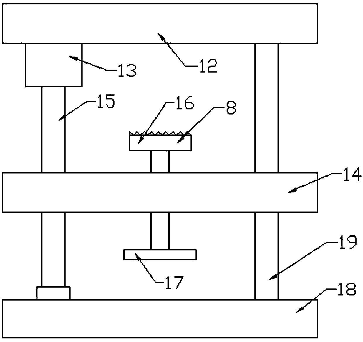
[0030] Such as Figure 1-2 As shown, one end of fixed seat 1 is provided with positioning mechanism, and this positioning mechanism comprises fixed plate 14, screw rod 15 and fixed rod 19, and the top of fixed plate 14 is provided with screw hole, is connected with screw rod 15 by screw thread in this screw hole, and screw rod 15 is fixed with a positioning plate 16 near the end of the fixed table 2, and the side of the positioning plate 16 facing the fixed table 2 is covered with rubber teeth 8, and the end of the screw rod 15 away from the fixed table 2 is fixed with a handle 17, and the bottom sides of the fixed plate 14 are respectively Be provided with screw hole and connection hole, be connected with screw rod 15 by thread in this screw hole, one end of screw rod 15 near fixed platform 2 stretches into No. Counter motor 13, the output shaft of positive and negative motor 13 is connected screw rod 15 by coupling.
[0031] In this embodiment, by setting the positioning me...
Embodiment 3
[0033] Such as Figure 1-6 As shown, the bottom end of the fixed table 2 is equipped with a rotating shaft 3 on the side facing the positioning mechanism. The fixed table 2 is connected to the fixed seat 1 through the rotating shaft 3. One side of the fixed seat 1 is obliquely installed with a No. 1 cylinder 10, and the same side of the fixed table 2 A fixed block 9 is fixed, and the end of the piston rod of the No. 1 cylinder 10 is connected to the fixed block 9 through a connecting pin; a No. 1 fixed seat 12 is fixed in the No. 2 cavity 11 of the fixed seat 1, and the positive and negative motor 13 is installed on the No. 1 fixed seat. On 12, the screw rod 15 that is connected with positive and negative motor 13 stretches out one end of No. 2 cavity 11 and is installed on No. 2 fixed seat 18 through bearing; The upper and lower ends of one side are fixed with rubber teeth 8; the fixed seat 1 is a square setting.
[0034] In this embodiment, by setting the rotating shaft 3 a...
PUM
 Abstract
Description
Claims
Application Information