
Rotor punching sheet of permanent magnet synchronous motor

A permanent magnet synchronous motor and rotor punching technology, which is applied to synchronous machine parts, magnetic circuits, electrical components, etc., can solve the problems of heavy rotor punching structure, inconvenient clamping, and bulky structure

Pending Publication Date: 2021-05-18
环一军
View PDF0 Cites 0 Cited by
  • Summary
  • Abstract
  • Description
  • Claims
  • Application Information

AI Technical Summary

Problems solved by technology

[0003] The stator part of a permanent magnet synchronous motor is generally composed of rotor punches and coils, but the structure of the rotor punches of the previous permanent magnet synchronous motors is relatively bulky, and most of them are integrally formed, which is not easy to disassemble and maintain. The rotor of the existing permanent magnet synchronous motor The stamping structure is bulky and not easy to clamp, and now the rotor stamping of the permanent magnet synchronous motor is urgently needed to solve the above-mentioned problems

Method used


Image

  • Rotor punching sheet of permanent magnet synchronous motor
  • Rotor punching sheet of permanent magnet synchronous motor
  • Rotor punching sheet of permanent magnet synchronous motor

Examples


Embodiment Construction

[0020] In order to make the technical means, creative features, goals and effects achieved by the present invention easy to understand, the present invention will be further described below in conjunction with specific embodiments.

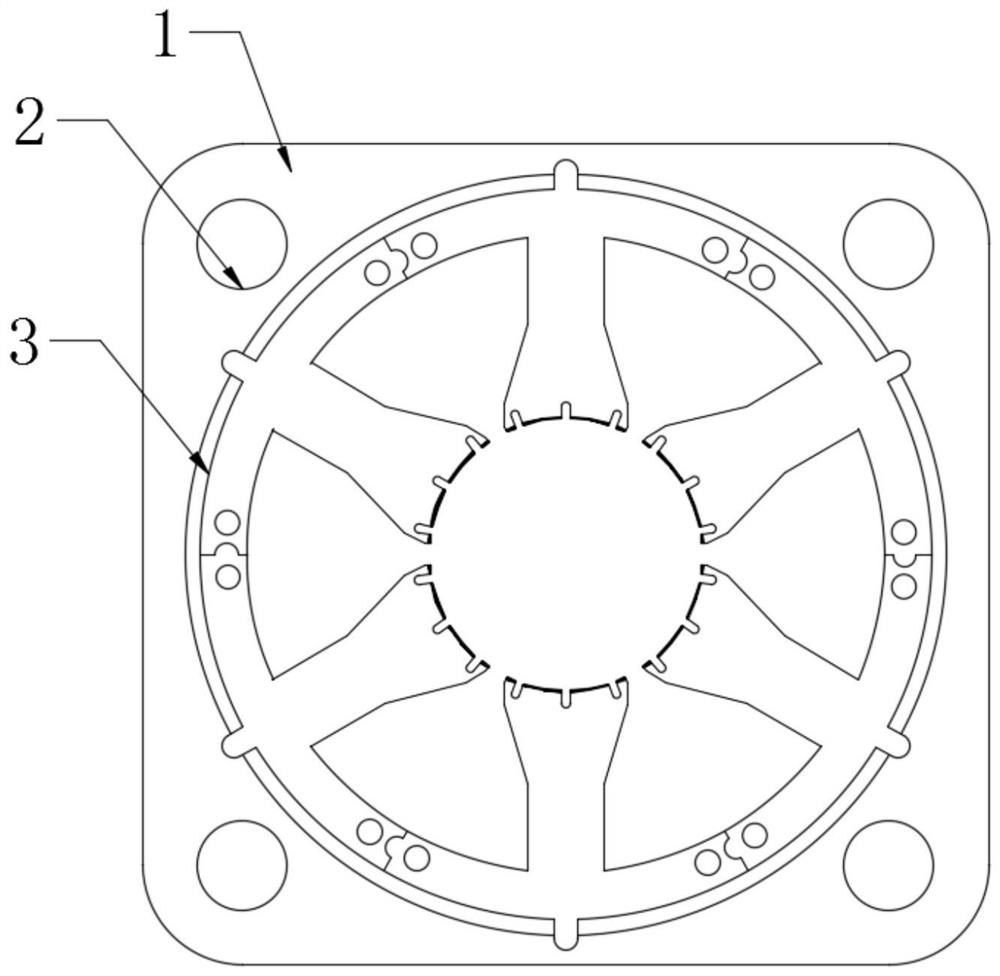
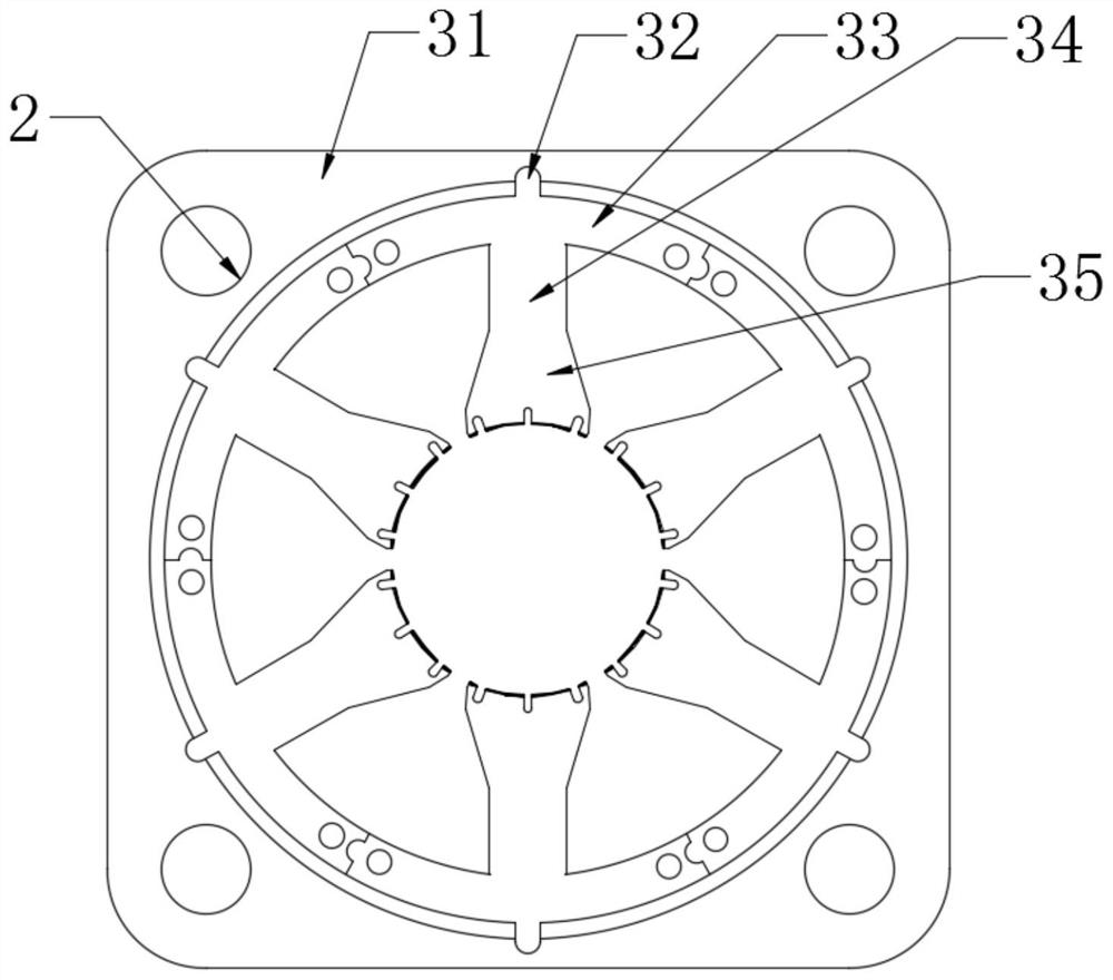
[0021] see Figure 1-Figure 4 , the present invention provides a technical solution: the rotor punching of the permanent magnet synchronous motor includes a punching main body 1, a pin hole 2 and a lightweight and easy-to-fit mechanism 3, the punching main body 1 is provided with a pin hole 2, and the punching body 1 There is a light-weight and easy-to-install mechanism 3 inside.

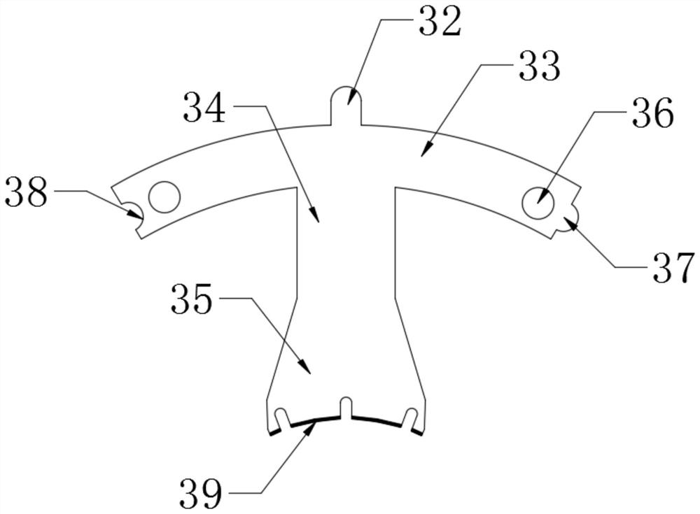
[0022] Lightweight and easy to install. The mechanism 3 includes a stator yoke 31, a first chuck 32, a splicing rod 33, a connecting rod 34, a pole piece 35, a positioning bump 36, a second chuck 37, a groove 38 and a lubricating film 39. A stator yoke 31 is installed on the outer side of the main body 1 of the punching sheet, and a pole shoe 35 is installed on the inn...


PUM

PropertyMeasurementUnit
Radianaaaaaaaaaa

Abstract

The invention provides a rotor punching sheet of a permanent magnet synchronous motor, which comprises a stator magnet yoke, a first clamping head, a splicing rod, a connecting rod, a pole shoe, a positioning convex block, a second clamping head, a groove and a lubricating film, and is characterized in that the stator magnet yoke is assembled on the outer side of a punching sheet main body, the pole shoe is assembled on the inner side of the stator magnet yoke, the connecting rod is assembled on the upper side of the pole shoe, and the splicing rod is assembled on the upper side of the connecting rod; a first clamping head is assembled on the upper side of the splicing rod, a second clamping head is assembled on the right side of the splicing rod, a groove is formed in the left side of the splicing rod, positioning protruding blocks are assembled on the left side and the right side of the splicing rod, and a lubricating film is arranged on the lower side of the pole shoe.Through the design, the problem that the rotor punching sheet of the original permanent magnet synchronous motor is heavy in structure and inconvenient to clamp is solved. The light weight effect of the rotor punching sheet is improved, clamping is facilitated, and later maintenance is facilitated.

Description

technical field [0001] The invention relates to a rotor punch of a permanent magnet synchronous motor, which belongs to the technical field of production and processing of the permanent magnet synchronous motor. Background technique [0002] The permanent magnet synchronous motor is a synchronous motor that is excited by a permanent magnet to generate a synchronous rotating magnetic field. The permanent magnet acts as a rotor to generate a rotating magnetic field. The three-phase stator winding reacts through the armature under the action of the rotating magnetic field to induce a three-phase symmetrical current. At this time, the kinetic energy of the rotor is converted into electric energy, and the permanent magnet synchronous motor is used as a generator; in addition, when the three-phase symmetrical current is passed into the stator side, since the three-phase stators have a difference of 120 in space, the three-phase stator currents rotate in space Magnetic field, the r...

Claims


Application Information

Patent Timeline
IPC IPC(8): H02K1/14H02K21/02
CPCH02K1/148H02K21/02
Inventor 环一军
Owner 环一军
Learn More