Cantilever beam supporting device and preparation method thereof

A support device and cantilever beam technology, which is applied in the direction of signal devices, power devices, transportation and packaging, etc., can solve problems such as easy breakage and self-heavyness, and achieve the effects of eliminating quality accidents, good fatigue performance, and avoiding quality risks

Inactive Publication Date: 2018-04-03
ZHUZHOU TIMES NEW MATERIALS TECH
View PDF5 Cites 5 Cited by
  • Summary
  • Abstract
  • Description
  • Claims
  • Application Information

AI Technical Summary

Problems solved by technology

[0006] The present invention aims to propose a cantilever beam support device and its manufacturing process, which can solve the problems of the existing cantilever beam support products such as large self-weight, resonance between the product and the frame, and easy breakage, and avoid major quality accidents

Method used


Image

  • Cantilever beam supporting device and preparation method thereof
  • Cantilever beam supporting device and preparation method thereof

Examples


Embodiment 1

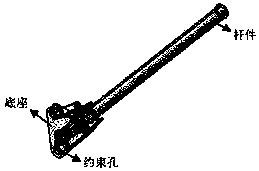
[0044] Such as figure 1 As shown, the cantilever beam supporting device of this embodiment includes a base and a rod connected to the base. The base is provided with several holes for fixing the supporting device on the frame of a car, for example. The thickness of the base can be set between 10-50mm. The number of holes is preferably 3-4. A number of metal gaskets can be added or removed in the hole. The rod is also provided with a number of fixed wings, which can be used to fix the supported parts. The number of wing plates is preferably 3 or more, for example 3-5. The width of the wing plate can be designed to be about 60mm. The rod is preferably tubular, the outer diameter of the tube can be between 40-100mm, and the thickness of the tube wall can be between 2-12mm.

[0045] The following describes the preparation of the overall molding method such as figure 1 The method of the cantilever beam support device is shown.

[0046] Step 1: Plasticize the resin through a...

Embodiment 2

[0054] This embodiment is prepared in an integral molding manner by molding and injection molding. figure 1 Basically the same structure as the method of cantilever beam support device.

[0055] Step 1: Prepare a thermoplastic continuous fiber-reinforced nylon composite material sheet with a continuous fiber weight content of 55%, wherein the fiber is a basalt continuous fiber.

[0056] Step 2: Prepare fiber-reinforced nylon composite pellets with good fluidity with a fiber weight content of 50% by melt dipping and pultrusion, wherein the fiber is glass fiber with a length of about 80mm.

[0057] Step 3: Cut the sheet prepared in step 1, put it into an oven to bake and heat, the baking temperature is 280°C, and the baking time is 1min to soften the material, and then put it into a mold.

[0058] Step 4: Bake the pellets prepared in step 2 at 120°C for 2 hours, control the moisture content below 0.2%, then vacuum-introduce the material into the hopper, and inject the mold into...

Embodiment 3

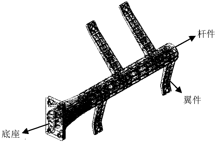
[0063] Such as figure 2 As shown, the cantilever beam supporting device in this embodiment includes a base and a rod, and the rod is inserted into the base to form a connection. Adhesives such as epoxy or polyurethane adhesives can be used to secure the rods to the base. The base is provided with several holes for fixing the supporting device on the frame of a car, for example. A number of metal gaskets can be added or removed in the hole. The thickness of the base can be set between 20-200mm. The number of holes is preferably 3-4. The rod is preferably tubular, the outer diameter of the tube can be between 40-100mm, and the thickness of the tube wall can be between 2-12mm.

[0064] In this embodiment, the base rods are manufactured separately, and then assembled into such figure 2 The cantilever beam support shown. In particular, in this embodiment, the fiber-reinforced epoxy resin is used to mold the base, and the fiber-reinforced epoxy resin is wound or extruded to ...


PUM

PropertyMeasurementUnit
lengthaaaaaaaaaa
lengthaaaaaaaaaa
thicknessaaaaaaaaaa

Abstract

The invention belongs to the field of automobile manufacturing, and particularly provides a cantilever beam supporting device and a preparation method thereof. The cantilever beam supporting device comprises a base and a rod piece connected with the base, wherein the base and the rod piece are made of fiber-reinforced resin-based composite materials. The cantilever beam supporting device has the characteristic of lightweight so that the weight of a vehicle can be reduced, and the energy-saving and emission-reducing effects can be achieved. Meanwhile, the cantilever beam supporting device can effectively reduce the resonance effect of the cantilever beam supporting device and a vehicle frame, breaking can be prevented, quality risks are avoided, and the preparation method is simple and feasible.

Description

technical field [0001] The invention relates to the field of automobile manufacturing, in particular to a cantilever beam support device and a manufacturing method thereof. Background technique [0002] As the global shortage of resources intensifies and the climate warms, limiting carbon emissions is an effective means to slow down the depletion of global oil energy and the deterioration of the natural ecological environment. Especially in the automobile industry, in order to consolidate and improve the future international competitiveness of the automobile industry, developed countries in the automobile industry such as Europe, America and Japan are taking active measures to promote and promote the development of automobile energy-saving technology and improve the fuel economy level of automobiles. According to European and American standards, China has also started the work of reducing vehicle emissions, but China's task is quite severe. In China, by 2016, national V emi...

Claims


Application Information

Patent Timeline
Patent Type & Authority Applications(China)
IPC IPC(8): B62D25/16B60Q1/00B60R3/00B60K15/067B60R16/04B60R13/10C08L23/12C08L77/00C08L63/00C08L77/02C08L77/10C08K7/10C08K7/06
CPCB62D25/166B60K15/067B60Q1/00B60R3/00B60R13/105B60R16/04C08K7/06C08K7/10C08K2201/004C08L77/02C08L2205/16C08L23/12C08L77/00C08L63/00C08L77/10
Inventor 张伟杨海洋郑梯和王全兵李旭武刘爱学黄安民
Owner ZHUZHOU TIMES NEW MATERIALS TECH
Why Eureka
Try Eureka