
Binding device for printed matters

A technology for printed matter and piston plate, which is applied in the field of printing and binding, and can solve problems such as affecting the effect of perfect binding, paper misalignment, and uneven paper.

Active Publication Date: 2019-03-29
重庆市骏煌印务有限公司
View PDF7 Cites 4 Cited by
  • Summary
  • Abstract
  • Description
  • Claims
  • Application Information

AI Technical Summary

Problems solved by technology

[0003] Now the commonly used binding method is to use glue binding, that is, to use the glue binding machine to apply glue to the side of the paper to bind the paper, but there are still some shortcomings: because the paper is piled up on the workbench, the paper at a high place will be along the Sliding around the sides, resulting in unevenness of the paper, causing the paper to be misaligned during glue binding, thus affecting the effect of glue binding

Method used


Image

  • Binding device for printed matters

Examples


Embodiment 1

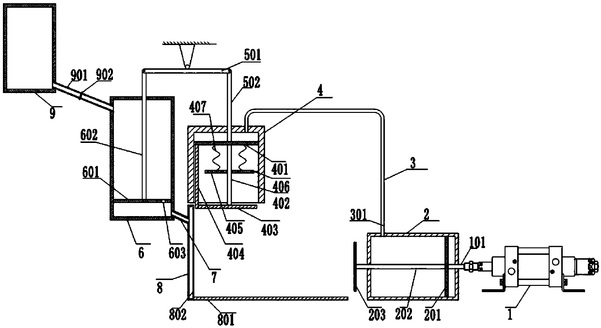
[0022] A binding device for printed matter, such as figure 1 As shown, including the frame, the frame is fixed from left to right with a glue storage tank 9, a glue tank 6, a pressure tank 4, an air tank 2 and a hydraulic cylinder 1. The pressure tank 4 is provided with a fixed on the frame Working part, the working part is L-shaped. The working part includes a third baffle 801 horizontally arranged directly below the pressure box 4 and a second baffle 8 located on the left side of the third baffle 801 and vertically arranged. 8 has a hollow interior and a number of glue outlets 802 are evenly distributed on the right side. The left end of the third baffle 801 is welded to the lower end of the second baffle 8.

[0023] A first piston plate 201 is slidably connected to the inside of the air box 2. The piston rod 101 of the hydraulic cylinder 1 is slidably fitted with the right wall of the air box 2 and welded to the right wall of the first piston plate 201. The left side of the ai...


PUM


Abstract

The invention relates to the technical field of printing and binding, in particular to a binding device for printed matters. The binding device for the printed matters comprises a machine frame and ahydraulic cylinder which is fixed on the machine frame, a air box, a pressing box, a glue box and a working portion are fixed on the machine frame, the hydraulic cylinder is connected with the air box, the air box and the glue box are located on the two sides of the pressing box respectively, the working portion is located under the pressing box, an air pipe is located between the air box and thepressing box and makes the air box communicated with the pressing, a guide pipe is located between the glue box and the working portion and makes the glue box communicated with the working portion, alever which is matched with the machine frame in a rotating mode is arranged above the pressing box, a second supporting rod and a third connecting rod are hinged to the two ends of the lever, a second connecting rod and the third connecting rod are in vertical sliding fit with the pressure box and the glue box respectively, the working portion comprises a second baffle and a third baffle, and a plurality of glue outlets facing the air box are formed in the second baffle. The binding device for the printed matters is used for binding the printed matters and side edges of the glued paper can bealigned.

Description

Technical field [0001] The invention relates to the technical field of printing and binding, in particular to a binding device for printed matter. Background technique [0002] In daily life, printed materials such as books can be seen everywhere. As people's demand for books is increasing, the demand for printing books has also increased. [0003] Nowadays, the commonly used binding method is to use perfect binding, that is, use a perfect binding machine to apply glue to the side of the paper to bind the paper, but there are still some shortcomings: because the paper is stacked on the workbench, the paper at high places will be The peripheral side slides, resulting in unevenness of the paper, causing the paper to be misaligned during glue binding, which affects the effect of glue binding. Summary of the invention [0004] The present invention intends to provide a binding device for printed matter that can be aligned evenly. [0005] In order to achieve the above objective, the tec...

Claims


Application Information

Patent Timeline
Patent Type & Authority Applications(China)
IPC IPC(8): B42C9/00
CPCB42C9/0018
Inventor 吴建均
Owner 重庆市骏煌印务有限公司
Learn More