
Normally-locked hydraulic disc brake device

A hydraulic and disc brake technology, applied in the field of normally-locking hydraulic disc brake devices, can solve the problems that the braking and unlocking processes of mobile equipment cannot be controlled at the same time, affect the driving direction, and cannot be braked at the same time, so as to solve the self-locking phenomenon and avoid rigidity. Impact, avoid instability effect

Active Publication Date: 2019-03-29
YANSHAN UNIV
View PDF8 Cites 3 Cited by
  • Summary
  • Abstract
  • Description
  • Claims
  • Application Information

AI Technical Summary

Problems solved by technology

Some movable equipment on the ship adopts the active braking method with brake universal wheels. The active braking method has great safety hazards under the condition of human operation, and each wheel needs to step on the brake when braking. The mobile equipment The braking and unlocking processes cannot be controlled at the same time, which is very inconvenient during use
The normally open hydraulic disc brake device used on the electric tricycle on the market, when the pressure oil provided by the hand brake pump acts on the two disc brakes at the same time, due to the different frictional resistance of the sealing device, the The pistons can't move at the same time, so they can't brake at the same time, resulting in serious dynamic load unbalanced load and affecting the driving direction

Method used


Image

  • Normally-locked hydraulic disc brake device
  • Normally-locked hydraulic disc brake device
  • Normally-locked hydraulic disc brake device

Examples


Embodiment Construction

[0020] In order to make the purpose, technical solutions and advantages of the embodiments of the present invention clearer, the technical solutions in the embodiments of the present invention will be clearly and completely described below in conjunction with the drawings in the embodiments of the present invention. Obviously, the described embodiments It is a part of embodiments of the present invention, but not all embodiments.

[0021] In describing the present invention, it is to be understood that the terms "radial", "axial", "upper", "lower", "top", "bottom", "inner", "outer" etc. indicate orientation Or the positional relationship is based on the orientation or positional relationship shown in the drawings, which is only for the convenience of describing the present invention and simplifying the description, and does not indicate or imply that the referred device or element must have a specific orientation, be constructed and operated in a specific orientation , and the...


PUM


Abstract

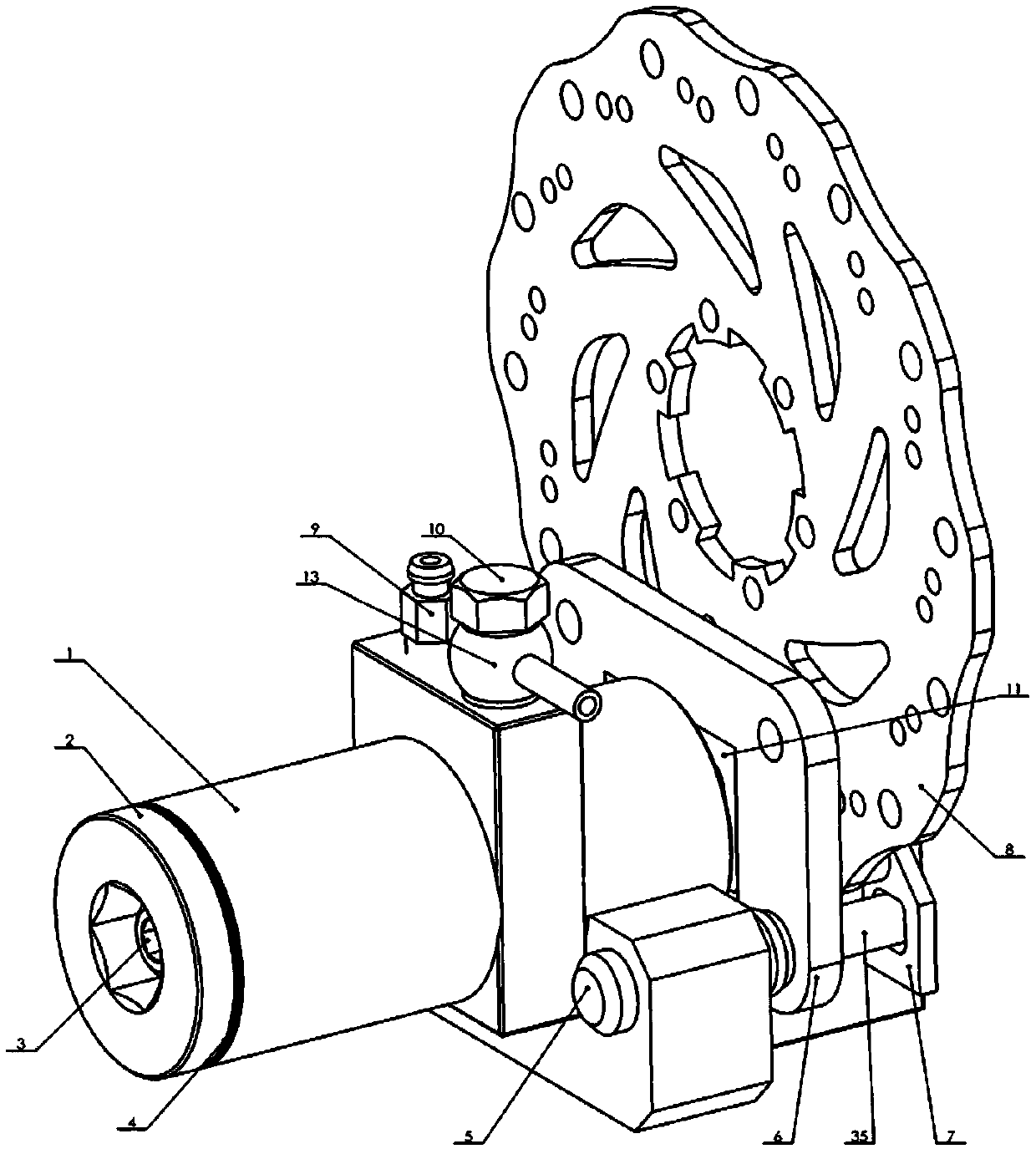
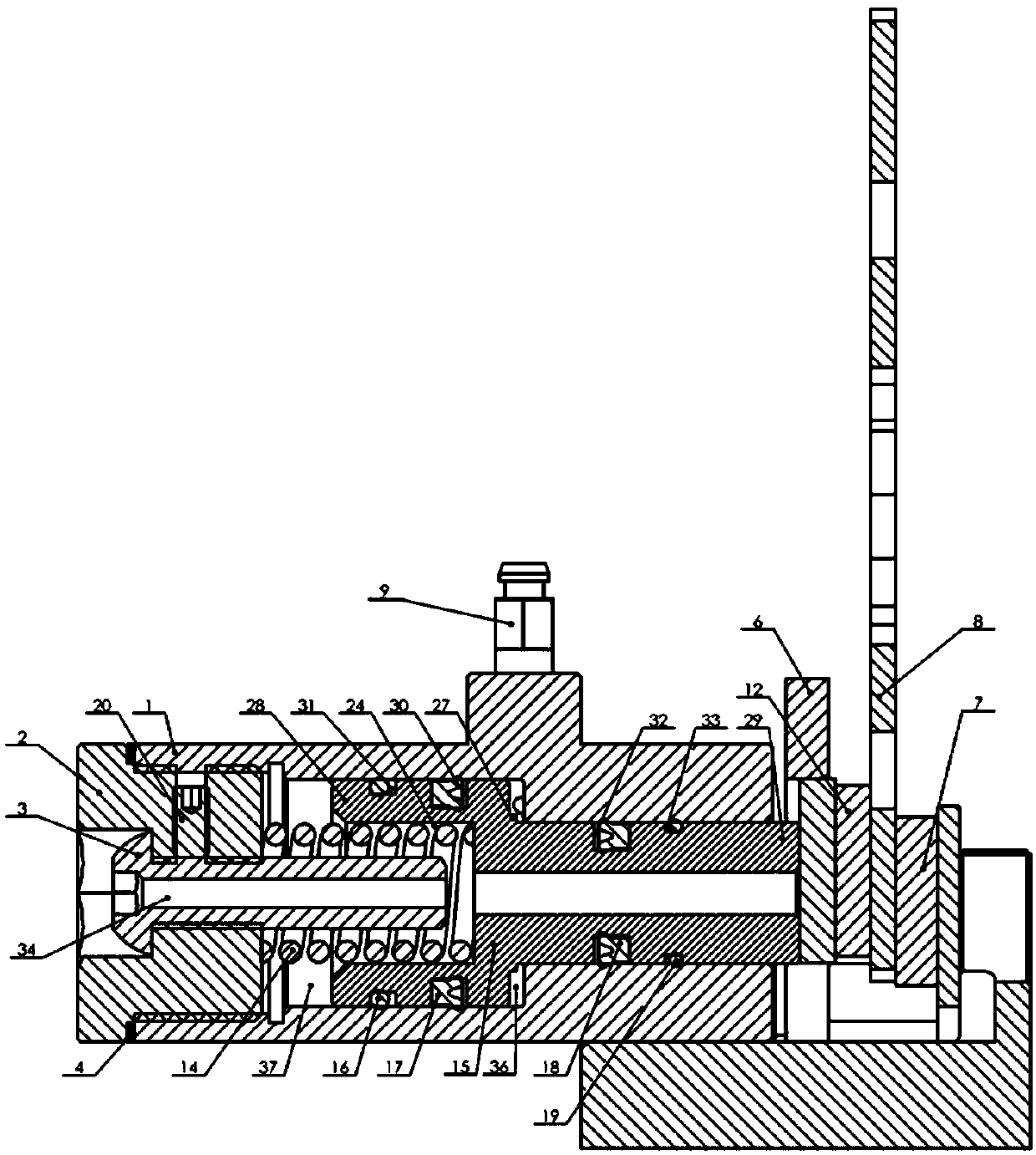
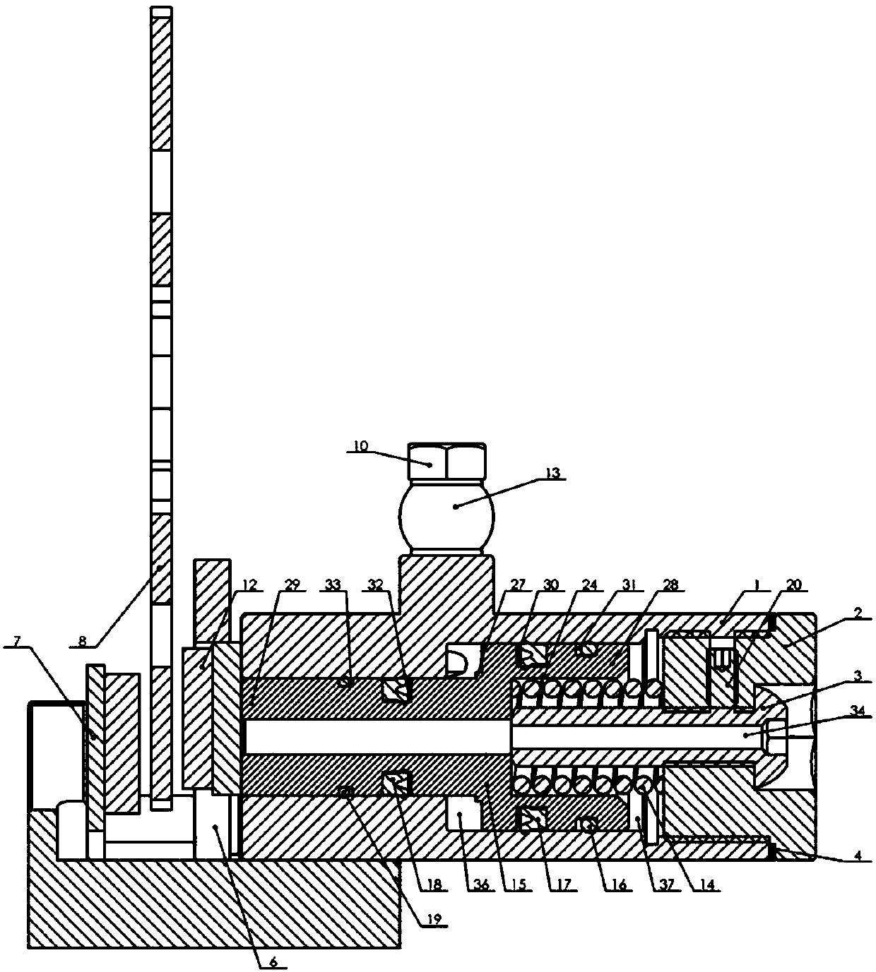
The invention discloses a normally-locked hydraulic disc brake device which comprises main clamp body, adjusting screw plug, limit screw, piston, limit location step, first sealing ring, second sealing ring, spring, third sealing ring, fourth sealing ring and positioning screw, step guiding hole and threaded hole are arranged in the main clamp body, adjusting screw plug is connected at bottom of the main clamp body through the threaded hole, adjusting gasket is arranged between the adjusting screw plug and the main clamp body, piston is pressed into the step guiding hole through matching, limit screw is connected at bottom of the adjusting screw plug through threads, spring is arranged in step guiding hole of the large shaft end, the piston is provided with first groove and second groove outside the large shaft end, first sealing ring and second sealing ring are respectively arranged in the first groove and the second groove, the piston is provided with third groove and fourth groove outside the small shaft end, and third sealing ring and fourth sealing ring are respectively arranged in the third groove and the fourth groove. The overall structure design of the invention is ingenious and convenient to use.

Description

technical field [0001] The invention relates to the technical field of hydraulic brakes, in particular to a constant-lock hydraulic disc brake device. Background technique [0002] Permanent lock brake means that the brake device is in the braking state without human operation. At present, it is mainly used in baby carriages, airport luggage carts, medical equipment, supermarket shopping carts, and other non-powered wheeled transport tools to prevent Personnel and equipment damage due to vehicle rolling on slopes, unintentional bumps and vibrations. At present, most of the strollers on the market adopt the active braking method, as shown in the patent No. CN200620149310.0 utility model, which requires the guardian to stop the stroller and step on the brake pedal to increase the static friction between the brake and the wheels. Realize the locking of the wheels. Once the guardian does not step on the brake pedal due to negligence, the brake device cannot be started. The pate...

Claims


Application Information

Patent Timeline
Patent Type & Authority Applications(China)
IPC IPC(8): B62B9/08B62B5/04
CPCB62B5/0452B62B9/08
Inventor 边辉刘灿王东华赵铁石
Owner YANSHAN UNIV
Learn More