Clip type caterpillar band stacking machine

A stacker and clip-type technology, which is applied in the field of stackers, can solve the problems of cumbersome discharging and feeding actions and affect the working efficiency of the stacker, and achieve the effects of convenient operation, convenient feeding and unloading, and low man-hour consumption

Pending Publication Date: 2019-03-29
SUZHOU IND PARK INSTREETCAREDIA SUZHOU
View PDF0 Cites 2 Cited by
  • Summary
  • Abstract
  • Description
  • Claims
  • Application Information

AI Technical Summary

Problems solved by technology

[0003] However, the stacker in the prior art has the following problems: (1) The existing feeding and unwinding method mainly relies on manual labor, and the lifting is adjusted by hydraulic manual up and down adjustment; (2) Stacking products need to use backing plates and rubber strips Auxiliary layers are stacked, and the action of discharging and feeding materials is cumbersome, which affects the working efficiency of the stacker

Method used


Image

  • Clip type caterpillar band stacking machine
  • Clip type caterpillar band stacking machine

Examples


Embodiment approach 1

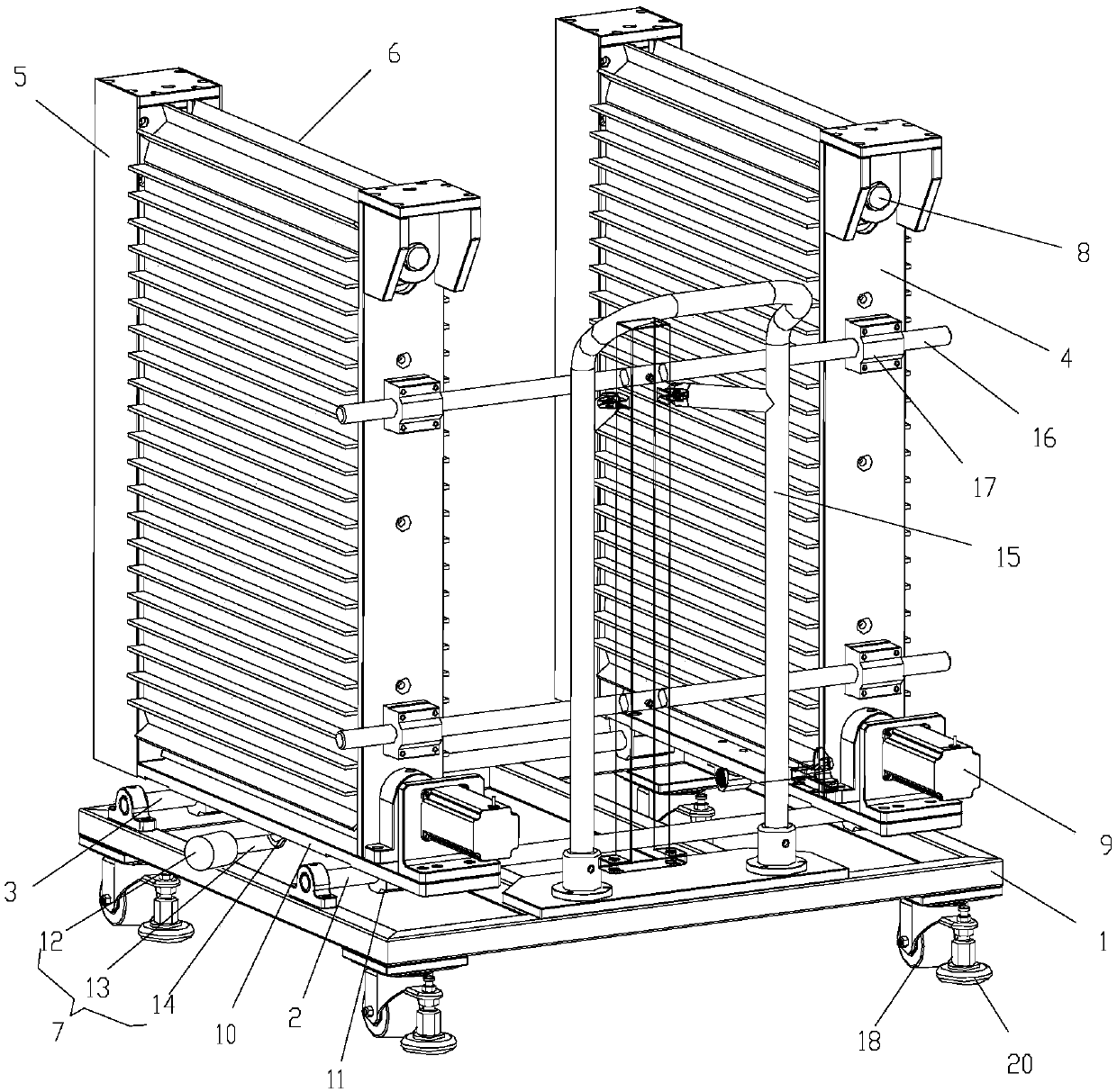
[0024] see Figure 1 to Figure 2 Shown is the first preferred embodiment of the clip-type crawler stacker of the present invention, the clip-type crawler stacker includes a base 1, a first support rod 2, a second support rod 3, and a first support plate 4 , the second support plate 5, the crawler belt 6 and the rotating mechanism 7, the first support rod 2 and the second support rod 3 are arranged relatively parallel on the base 1, as preferably, the base 1 is a square structure, and the first support The rod 2 and the second support rod 3 are circular rod-shaped structures, and the first support rod 2 and the second support rod 3 are arranged perpendicular to the base 1, and the first support plates 4 are respectively arranged at both ends of the first support rod 2 , the second support plate 5 is arranged at both ends of the second support rod 3 respectively, and a rotating shaft 8 is arranged between the first supporting plate 4 and the second supporting plate 5 at the same...

Embodiment approach 2

[0030] see figure 1Shown is the second preferred embodiment of the clip-type crawler stacker of the present invention. The difference between this embodiment and the first embodiment is that the crawler belt 6 is a grooved crawler belt, which is set as a groove The purpose of the crawler track: for the products to be stacked, it is necessary to use auxiliary layers such as backing plates and rubber strips to be stacked, and the life of auxiliary products such as backing plates and rubber strips is short, and frequent replacement of backing plates, rubber strips and other materials is required, which affects the stacking height. The working efficiency of the machine, accordingly, the present invention aims at the above-mentioned problems, and sets the crawler belt 6 as a slotted type, so that the product to be stacked can be fixed only by being stuck in the crawler belt 6, eliminating the need for The existing backing plate, rubber strip and other materials are used, and the wo...


PUM


Abstract

The invention relates to the technical field of stacking machines, in particular to a clip type caterpillar band stacking machine. The clip type caterpillar band stacking machine comprises a base, a first supporting rod, a second supporting rod, first supporting boards, second supporting boards, a caterpillar band and a rotary mechanism, wherein the first supporting rod and the second supporting rod are arranged on the base oppositely in parallel; the first supporting boards are arranged at two ends of the first supporting rod separately; the second supporting boards are arranged at two ends of the second supporting rod separately; a rotary shaft is arranged between the first supporting board and the second supporting board located at the same end; the caterpillar band is installed on therotary shafts; the rotary mechanism comprises a drive motor, a bidirectional lead screw and nuts; the nuts are in threaded connection with different thread sections at the two ends of the bidirectional lead screw separately; the nuts are fixedly connected with a bearing board; and one end of the bidirectional lead screw is connected with the output end of a drive motor fixed to the base. The cliptype caterpillar band stacking machine can conveniently load and unload materials, and are short in consumed man hour, stable in operation and long in service life.

Description

technical field [0001] The invention relates to the technical field of forklifts, in particular to a clip-type crawler forklift. Background technique [0002] The stacker has simple structure, flexible operation, good micro-movement, and high explosion-proof safety performance. It is suitable for operations in narrow passages and limited spaces, and is an ideal equipment for loading and unloading pallets in high-bay warehouses and workshops. It can be widely used in petroleum, chemical, pharmaceutical, textile, military, paint, pigment, coal and other industries, as well as in ports, railways, freight yards, warehouses and other places containing explosive mixtures, for loading, unloading, stacking and handling operations. It can greatly improve work efficiency, reduce the labor intensity of workers, and win opportunities for enterprises to compete in the market. [0003] However, the stacker in the prior art has the following problems: (1) The existing feeding and unwindi...

Claims


Application Information

Patent Timeline
Patent Type & Authority Applications(China)
IPC IPC(8): B65G15/14B65G23/22B65G15/58B65G57/11
CPCB65G15/14B65G15/58B65G23/22B65G57/11
Inventor 王素卿
Owner SUZHOU IND PARK INSTREETCAREDIA SUZHOU
Why Eureka
Try Eureka