
Automatic spinning equipment gluing mechanism, shaft transferring device and shaft transferring method

A technology of gluing mechanism and textile equipment, applied in the direction of reversing machine, textile and papermaking, other manufacturing equipment/tools, etc., can solve the problems of time-consuming, labor-intensive, low efficiency, and defective products

Pending Publication Date: 2019-03-29
GUANGDONG ESQUEL TEXTILES
View PDF0 Cites 3 Cited by
  • Summary
  • Abstract
  • Description
  • Claims
  • Application Information

AI Technical Summary

Problems solved by technology

The traditional yarn fixing method completely relies on manual adhesive tape, which is time-consuming, laborious, low efficiency, and inaccurate pasting. If the adhesive tape is not pasted properly, it will cause the problem of defective products.

Method used

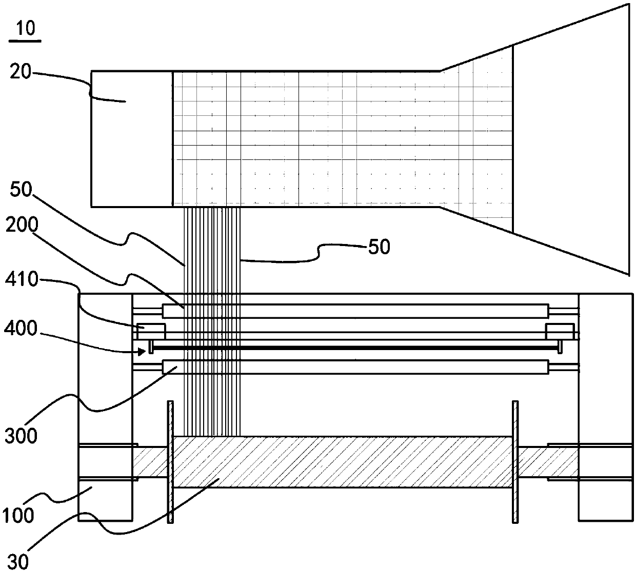
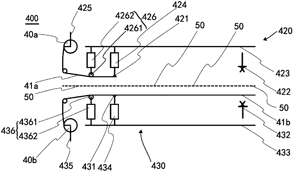

Image

  • Automatic spinning equipment gluing mechanism, shaft transferring device and shaft transferring method
  • Automatic spinning equipment gluing mechanism, shaft transferring device and shaft transferring method

Examples


Embodiment Construction

[0026] In order to facilitate the understanding of the present invention, the present invention will be described more fully below with reference to the associated drawings. Preferred embodiments of the invention are shown in the accompanying drawings. However, the present invention can be embodied in many different forms and is not limited to the embodiments described herein. On the contrary, these embodiments are provided to make the understanding of the disclosure of the present invention more thorough and comprehensive.

[0027] It should be noted that when an element is referred to as being “fixed” to another element, it can be directly on the other element or there can also be an intervening element. When an element is referred to as being "connected to" another element, it can be directly connected to the other element or intervening elements may also be present.

[0028] Unless otherwise defined, all technical and scientific terms used herein have the same meaning as...


PUM


Abstract

The invention discloses an automatic spinning equipment gluing mechanism, a shaft transferring device and a shaft transferring method. The automatic spinning equipment gluing mechanism comprises a gluing bracket, a first gluing part and a second gluing part, wherein the first gluing part comprises a first driving part, a first shearing part and a first gluing guide part; the first shearing part isconnected to one end of the first gluing guide part; a glue coiling block is mounted at the other end of the first gluing guide part; the first driving part is connected with the first gluing guide part in a sliding manner to drive glue paper on the guide coiling block to move for a preset length; the second gluing part comprises a second driving part, a second shearing part and a second gluing guide part; the second gluing guide part and the first gluing guide part are oppositely arranged; the second shearing part is connected to one end of the second gluing guide part; the second driving part is connected with the second gluing guide part in a sliding manner to drive glue paper on the glue coiling block to move for a preset length. By adopting the automatic spinning equipment gluing mechanism, the purposes of high yarn fixing efficiency and precise glue paper pasting positions can be achieved.

Description

technical field [0001] The invention relates to the field of textile equipment, in particular to an automatic gluing mechanism for textile equipment, a shaft reversing device and a shaft reversing method. Background technique [0002] In the textile field, some textile equipment with drum winding, such as section warping machine, pulping machine, warping and pulping machine, etc., need to unwind the yarn wound on the drum to the empty weaving shaft. The process is called inversion. When reversing the shaft, it is necessary to fix multiple yarns arranged side by side to ensure that the position of the yarns will not be confused when entering the next process. The traditional fixing of the yarn when the beam is inverted is realized by manual adhesive tape, and the manual movement along the weaving beam left and right completes the 1800-2000mm long adhesive tape pasted on the yarn. The traditional yarn fixing method completely relies on manual adhesive tape, which has the pro...

Claims


Application Information

Patent Timeline
IPC IPC(8): D02H5/00D02H13/00
CPCD02H5/00D02H13/00
Inventor 文长华田柱安王允问晓锋
Owner GUANGDONG ESQUEL TEXTILES
Learn More