
Anti-thunder aviation obstruction beacon capable of using wind energy and solar energy

An aviation obstruction light and solar energy technology, which is applied in lighting applications, lighting and heating equipment, lighting devices, etc., can solve the problems that the power supply of aviation obstruction lights cannot achieve a continuous and stable effect and is not applicable, and achieves simple and fast installation, energy Convert Efficient Effects

Inactive Publication Date: 2019-03-29
SONGFEI IND GRP CO LTD
View PDF0 Cites 0 Cited by
  • Summary
  • Abstract
  • Description
  • Claims
  • Application Information

AI Technical Summary

Problems solved by technology

[0002] With the rapid development of social economy, airplanes are no longer out of reach, and many cities have gradually joined the ranks of low-altitude flights in open cities. However, skyscrapers, power towers, signal towers, and bridges are getting higher and higher. Urban low-altitude flight is an obstacle that cannot be ignored, so aviation obstruction lights are an essential guarantee to ensure the safety of low-altitude flights, but due to the inconvenient power supply in some places, aviation obstruction lights powered by conventional mains power are obviously not suitable, such as power towers , bridges, if only solar aviation obstruction lights are used, it is obvious that solar aviation obstruction lights can only collect energy during the day and will not work at night. The power supply of aviation obstruction lights cannot achieve a continuous and stable effect, so it is necessary to provide a wind energy solar lightning protection The type aviation obstruction light cooperates with solar energy and wind energy to provide a stable power supply for aviation obstruction lights during the day, and wind energy plays a role at night to continue to deliver power to aviation obstruction lights, and the aviation obstruction lights have their own lightning rods without external lightning protection devices

Method used


Image

  • Anti-thunder aviation obstruction beacon capable of using wind energy and solar energy

Examples


Embodiment Construction

[0015] The embodiments of the present invention will be described in detail below with reference to the accompanying drawings, but the present invention can be implemented in many different ways defined and covered by the claims.

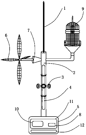
[0016] Such as figure 1 as shown, figure 1 It is a structural diagram of a wind energy solar lightning protection aviation obstruction light of the present invention, a wind energy solar lightning protection aviation obstruction light, including a lightning rod 1, a metal telescopic upper rod 2, a threaded triangular lock 3, a metal telescopic lower rod 4, a metal telescopic Rod box 5, fan blade 6, wind motor 7, rectification and voltage stabilization circuit 8, lamp body 9, single-chip microcomputer control system 10, PCB circuit board 11, battery pack 12.

[0017] Wherein, the lightning rod 1 is fixedly connected to the top of the metal telescopic upper rod 2, the metal telescopic upper rod 2 is fixedly connected to the metal telescopic lower rod...


PUM


Abstract

The invention provides an anti-thunder aviation obstruction beacon capable of using wind energy and solar energy. The anti-thunder aviation obstruction beacon comprises a lightning rod, an upper metaltelescoping rod, a threaded triangular lock, a lower metal telescoping rod, a metal telescoping rod box, wind blades, a wind energy motor, a rectifying voltage stabilizing circuit, a lamp body, a single chip micro-controller system, a PCB and a battery pack, wherein the lightning rod is connected to the rod tip of the upper metal telescoping rod, the upper metal telescoping rod is connected withthe lower metal telescoping rod through the threaded triangular lock, the metal telescoping rod box is fixedly connected to the bottom of the lower metal telescoping rod, the wind blades are arrangedon a rotor of the wind energy motor, the rectifying voltage stabilizing circuit, the single chip micro-controller system are arranged on the PCB, the lamp body is arranged on the upper portion of theupper metal telescoping rod, and the PCB and the battery pack are arranged in the metal telescoping rod box. The anti-thunder aviation obstruction beacon has the advantages that by using the wind blades, the wind energy motor, the rectifying voltage stabilizing circuit and the lamp body, the whole system has power, and the system saves more energy and is more efficient.

Description

technical field [0001] The invention is applied to the field of airport lamps, in particular to a wind energy solar lightning protection type aviation obstruction light. Background technique [0002] With the rapid development of social economy, airplanes are no longer out of reach, and many cities have gradually joined the ranks of low-altitude flights in open cities. However, skyscrapers, power towers, signal towers, and bridges are getting higher and higher. Urban low-altitude flight is an obstacle that cannot be ignored, so aviation obstruction lights are an essential guarantee to ensure the safety of low-altitude flights, but due to the inconvenient power supply in some places, aviation obstruction lights powered by conventional mains power are obviously not applicable, such as power towers , Bridges, if only solar aviation obstruction lights are used, it is obvious that solar aviation obstruction lights can only collect energy during the day and do not work at night. T...

Claims


Application Information

Patent Timeline
IPC IPC(8): F21S9/02F21S9/03F21S9/04F21V23/00F21V23/02F21V21/22F21V25/00F21W111/04
CPCF21S9/026F21S9/03F21S9/043F21V21/22F21V23/003F21V23/02F21V25/00F21W2111/04
Inventor 宋照飞袁启斌
Owner SONGFEI IND GRP CO LTD
Features
  • Generate Ideas
  • Intellectual Property
  • Life Sciences
  • Materials
  • Tech Scout
  • Unparalleled Data Quality
  • Higher Quality Content
  • 60% Fewer Hallucinations
Learn More