
Method for Manufacturing a Nanostructured Inorganic/Organic Heterojunction Solar Cell

a solar cell and nano-organic technology, applied in the direction of solid-state devices, sustainable manufacturing/processing, final product manufacturing, etc., can solve the problems of stability, blockage of large-scale use of solar cells, and low manufacturing cost of solar cells, so as to facilitate the treatment of them and improve energy conversion efficiency

Inactive Publication Date: 2013-03-14
KOREA RES INST OF CHEM TECH
View PDF2 Cites 10 Cited by
  • Summary
  • Abstract
  • Description
  • Claims
  • Application Information

AI Technical Summary

Benefits of technology

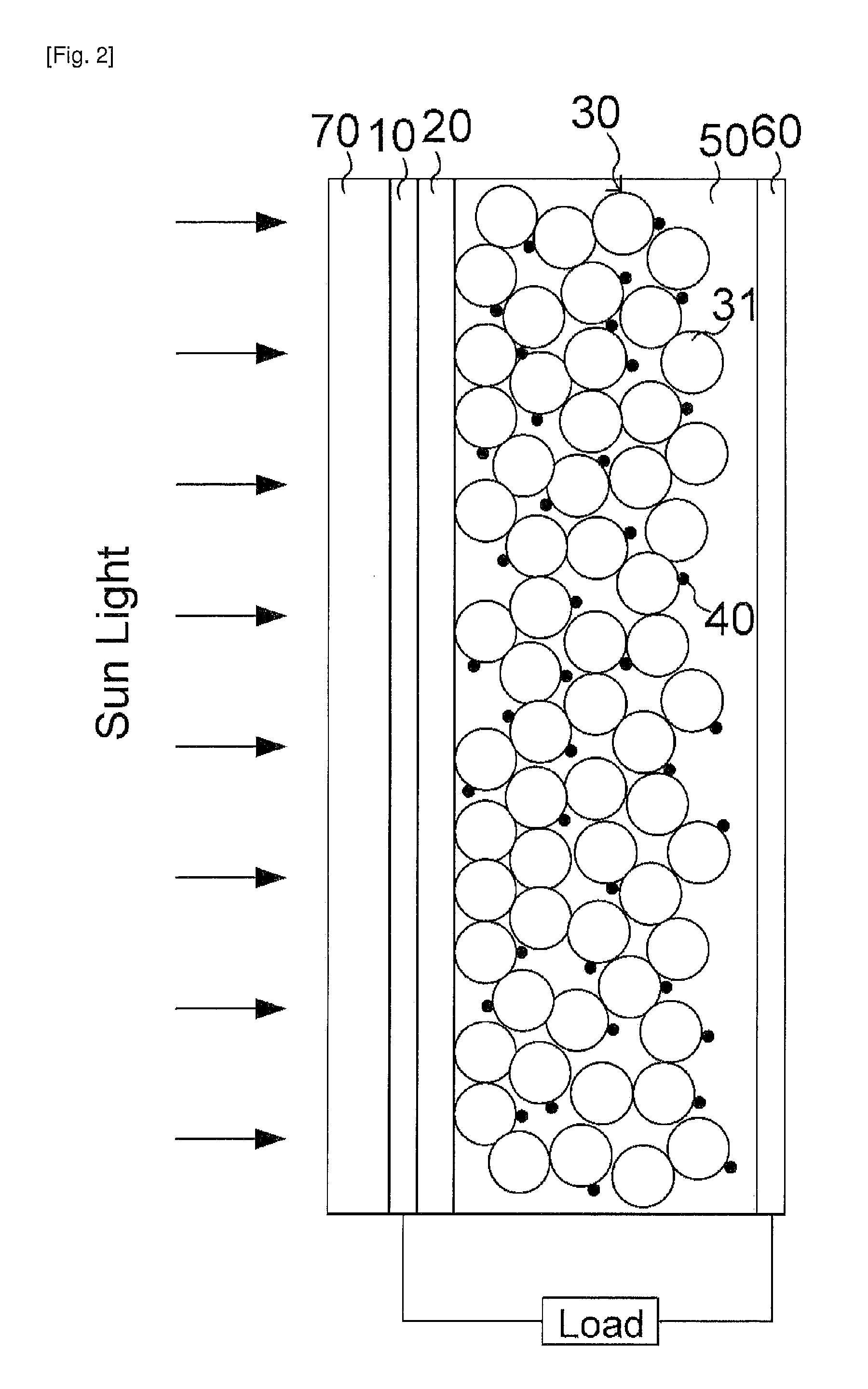
The present invention is about a new type of solar cell that uses an all-solid state nanostructured inorganic-organic heterojunction. This solar cell is made using quantum dot nano particles, a discontinuous layer, and a continuous layer. The cells are designed to have a structure that allows the inorganic semiconductor to generate the photoelectron and the hole transporting organic material to move the photoelectron. This new design is stable and can be mass-produced using inexpensive raw materials without using expensive ruthenium based dyes. The solar cells can absorb a larger amount of solar light with the same light intensity as compared to dye sensitized solar cells and organic solar cells. The energy conversion efficiency of the new solar cells is 5% or higher.

Problems solved by technology

However, since these inorganic semiconductors based solar cells require a significantly high-purity purified material for high efficiency, a large amount of energy is consumed in purifying a raw material, and expensive processing equipment is required during a single crystallization process or a thinning process using the raw material, such that there is a limitation in lowering a manufacturing cost of the solar cell, thereby blocking large-scale use of the solar cell.
However, there are problems in stability according to time by a volatile liquid electrolyte and reducing cost due to using a high-cost ruthenium (Ru) based dye.
Since a distance at which the exciton generated in the electron donor may move is about 10 nm, which is significantly short, photo active organic materials may not be thickly laminated, such that optical absorption spectra was low and the efficiency was low.
However, the organic photovoltaic has a problem that a structure of BHJ is degraded by moisture in air or oxygen to rapidly decrease the efficiency thereof, that is, a problem in the stability of the solar cell.
When a technology of completely sealing the solar cell is introduced in order to solve this problem, the stability may be increased, but a cost may also be increased.
However, there was a problem in the stability of the cell such as a problem that efficiency of the cell was reduced by half after 3 days, or the like.
In this case, the cell has excessively low efficiency in addition to a problem generated by using CdSe which contains toxic Cd.

Method used


Image

  • Method for Manufacturing a Nanostructured Inorganic/Organic Heterojunction Solar Cell
  • Method for Manufacturing a Nanostructured Inorganic/Organic Heterojunction Solar Cell
  • Method for Manufacturing a Nanostructured Inorganic/Organic Heterojunction Solar Cell

Examples


preparing example 1

[0129]After a glass substrate on which tin oxide containing fluorine (first electrode) is coated (fluorine-doped F-substrate) was cut at a size of 25×25 mm, end portions thereof were etched to partially remove FTO, similarly to FIG. 5.

[0130]A dense structured TiO2 thin film having a thickness of 50 nm was prepared by a spray pyrolysis method (SPM) on the cut and partially etched FTO substrate as a recombination preventing film. The SPM was performed using a titanium acetylacetonate (TAA): EtOH(1:9v / v %) solution, and a thickness was controlled by repeating a method of spraying the solution for 3 seconds and stopping for 10 seconds on the FTO substrate positioned on a hot plate maintained at a temperature of 450° C.

[0131]5 ml of ethyl cellulose solution in which 10 weight % of ethyl cellulose is dissolved in ethyl alcohol was added to TiO2 powder having an average particle size of 60 nm (preparing by hydrothermal treatment of titanium perocomplex aqueous solution in which 1% is disso...

preparing example 2

[0136]After a glass substrate on which tin oxide containing fluorine (first electrode) is coated (fluorine-doped F-doped SnO2, 8 ohms / sq, Pilkington, hereinafter, FTO substrate) was cut at a size of 25×25 mm, end portions thereof were etched to partially remove FTO similarly to FIG. 5.

[0137]A dense structured TiO2 thin film having a thickness of about 50 nm was prepared by a spray pyrolysis method (SPM) on the cut and partially etched FTO substrate as a recombination preventing film. The SPM was performed using a titanium acetylacetonate (TAA):EtOH(1:9v / v %) solution, and a thickness was controlled by repeating a method of spraying the solution for 3 seconds and stopping for 10 seconds on the FTO substrate positioned on a hot plate maintained at a temperature of 450° C.

[0138]5 ml of ethyl cellulose solution in which 10 weight % of ethyl cellulose is dissolved in ethyl alcohol was added to TiO2 powder having an average particle size of 60 nm (preparing by hydrothermal treatment of ti...


PUM

PropertyMeasurementUnit
particle sizeaaaaaaaaaa
specific surface areaaaaaaaaaaa
thicknessaaaaaaaaaa

Abstract

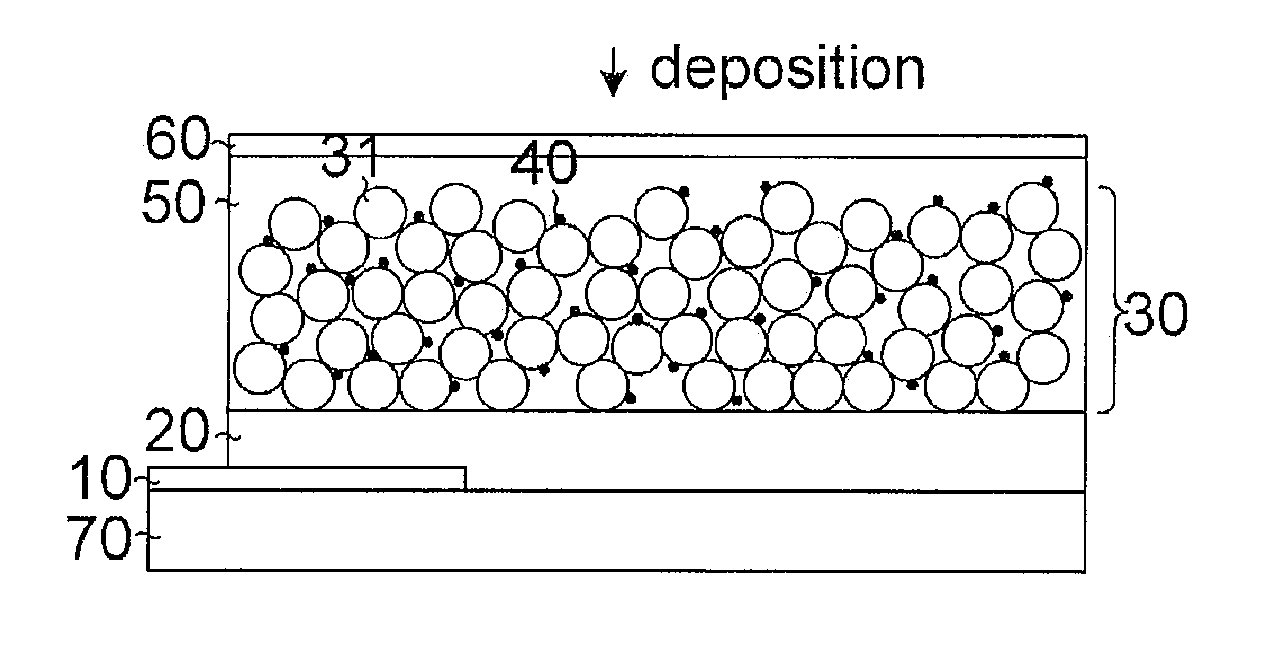
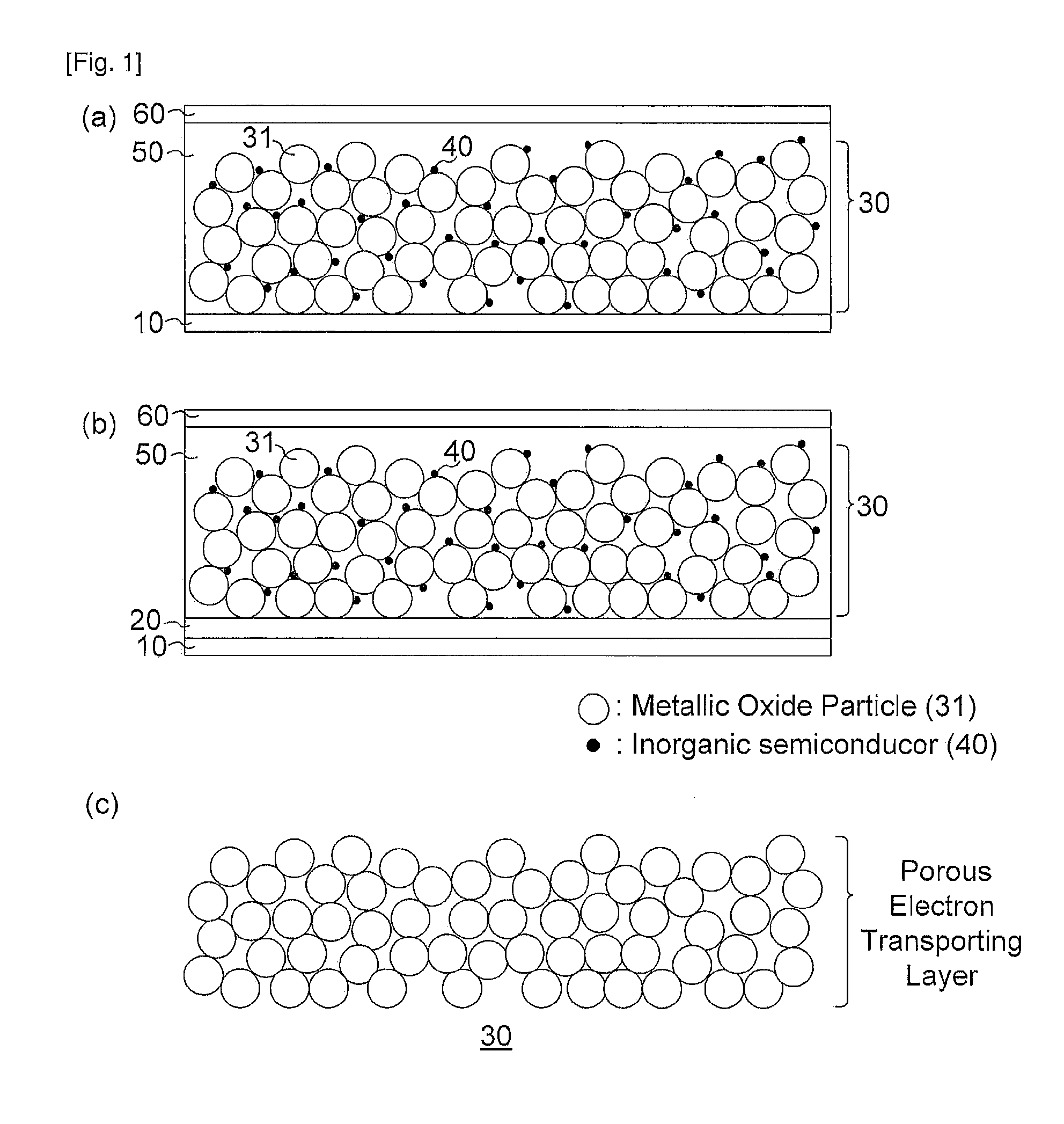
Provided is a method for manufacturing a significantly high efficient solar cell having a novel structure and superior stability, and which can be mass-produced from an inexpensive material from an inexpensive material for enabling the easy commercial availability thereof. More particularly, the method of the present invention comprises the following step: (a) depositing slurry containing metal oxide particles and heat-treating the slurry to form a porous electron transporting layer; (b) forming inorganic semiconductors on surfaces of the metal oxide particles for the porous electron-transporting layer; and (c) impregnating the porous electron-transporting layer having the inorganic semiconductor formed thereon with a solution containing an organic photovoltaic material so as to form a hole transporting layer.

Description

TECHNICAL FIELD[0001]The following disclosure relates to an all-solid state nanostructured inorganic-organic heterojunction solar cell, and a method of manufacturing the same, and particularly, to a new solar cell having high efficiency and excellent stability according to time and manufactured at low cost using an inexpensive material and an inexpensive process by combining an advantage of an inorganic thin-film solar cell capable of easily absorbing solar energy of a wide band from visible light to near infrared light and an advantage of an organic solar cell capable of being manufactured at a low cost by a solution process with a structure of a dye-sensitized solar cell (DSSC) that is cheap and has high efficiency, and a method of manufacturing the same.BACKGROUND ART[0002]In order to solve exhaustion of fossil energy and environmental problems due to using fossil energy, research into alternative energy source such as solar energy, wind energy, and hydro energy that is renewable...

Claims


Application Information

Patent Timeline
Patent Type & Authority Applications(United States)
IPC IPC(8): H01L51/48H01L51/46
CPCY02E10/542Y02E10/549H01L51/4226H01L51/0036Y02P70/50H10K85/113H10K30/151H10K30/50H01L31/04H01L31/06
Inventor SEOK, SANG ILIM, SANG HYUKCHANG, JEONG AHRHEE, JAE HUILEE, YONG HUIKIM, HI JUNG
Owner KOREA RES INST OF CHEM TECH
Learn More