Pressurized fluid flow system having multiple work chambers for a down-the-hole drill hammer and normal and reverse circulation hammers thereof

a technology of pressurized fluid and work chambers, which is applied in the direction of drilling accessories, earthwork drilling and mining, and well accessories. it can solve the problems of reducing the front and rear thrust areas, affecting the power of the hammer, and null exertion of pressurized fluid over this region of the piston

Active Publication Date: 2014-03-20
DRILLCO TOOLS
View PDF16 Cites 11 Cited by
  • Summary
  • Abstract
  • Description
  • Claims
  • Application Information

AI Technical Summary

Benefits of technology

[0017]a greater pressurized fluid consumption and as a result a higher power and a greater penetration rate,
[0018]a higher efficiency in the energy conversion process to provide an even higher power and even greater penetration rate, and

Problems solved by technology

One disadvantage of this design is that the pressure in the main drive chamber is equal in average to the supply pressure of the working fluid, which means that the work exerted by the pressurized fluid over this region of the piston is null, so that the power of the hammer is negatively affected.
Another disadvantage is the cross-sectional area occupied by the control rod, resulting in reduced front and rear thrust areas.
Since in this design the chamber formed between the forward piston head and the intermediate wall is continuously connected to the source of pressurized fluid, work exerted by this region of the piston is null.
The DTH drill hammers of the prior art described above have the drawback that they do not make use of the whole capacity of the additional drive and lifting chambers provided because at least one of these chambers is continuously connected to the source of pressurized fluid so the work exerted by the chamber is null.

Method used


Image

  • Pressurized fluid flow system having multiple work chambers for a down-the-hole drill hammer and normal and reverse circulation hammers thereof
  • Pressurized fluid flow system having multiple work chambers for a down-the-hole drill hammer and normal and reverse circulation hammers thereof
  • Pressurized fluid flow system having multiple work chambers for a down-the-hole drill hammer and normal and reverse circulation hammers thereof

Examples


Embodiment Construction
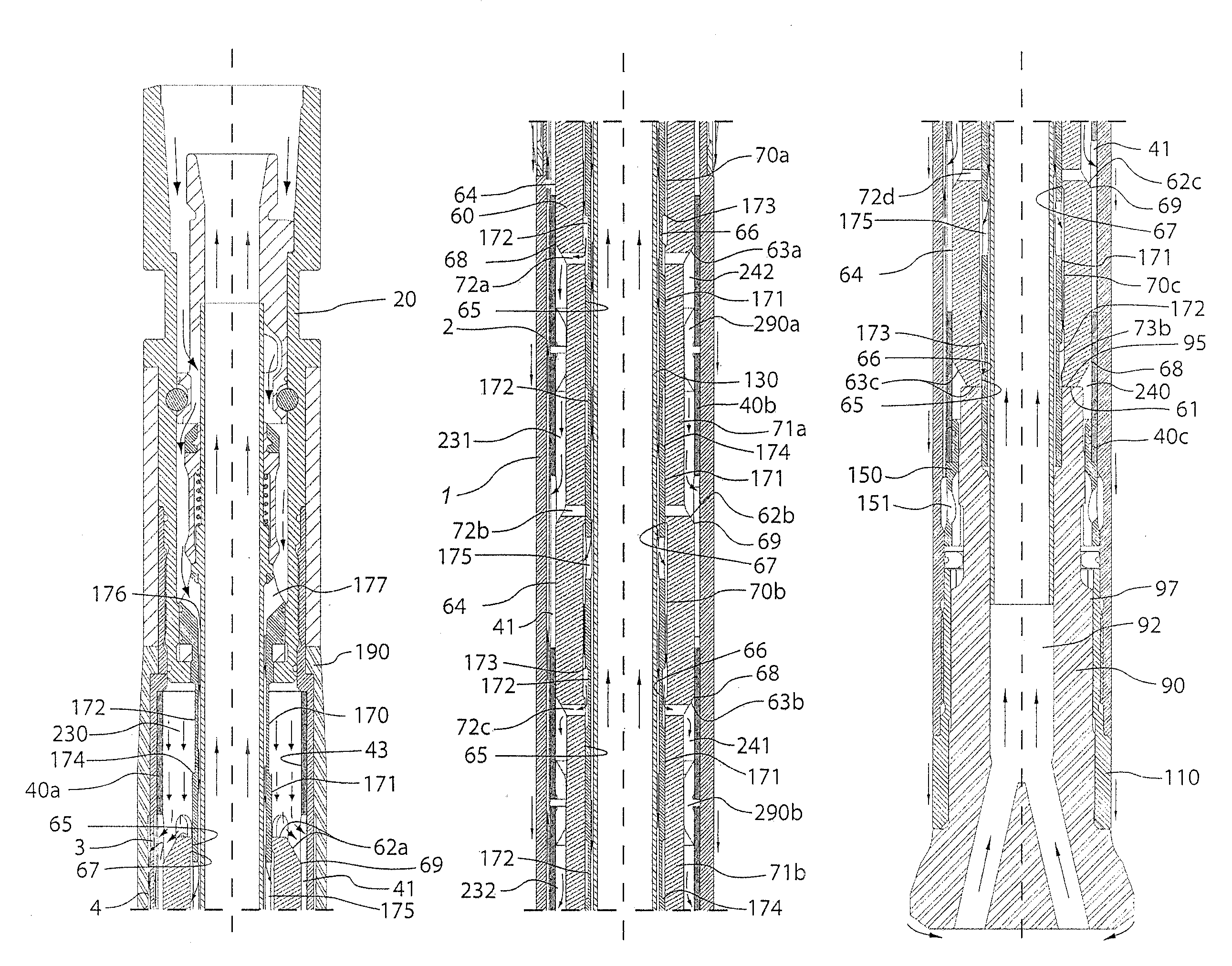
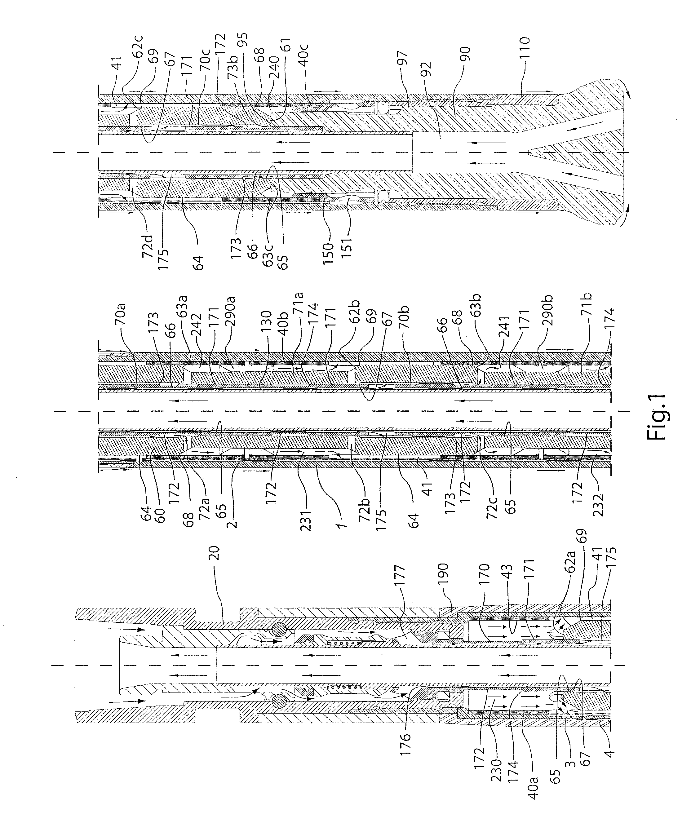
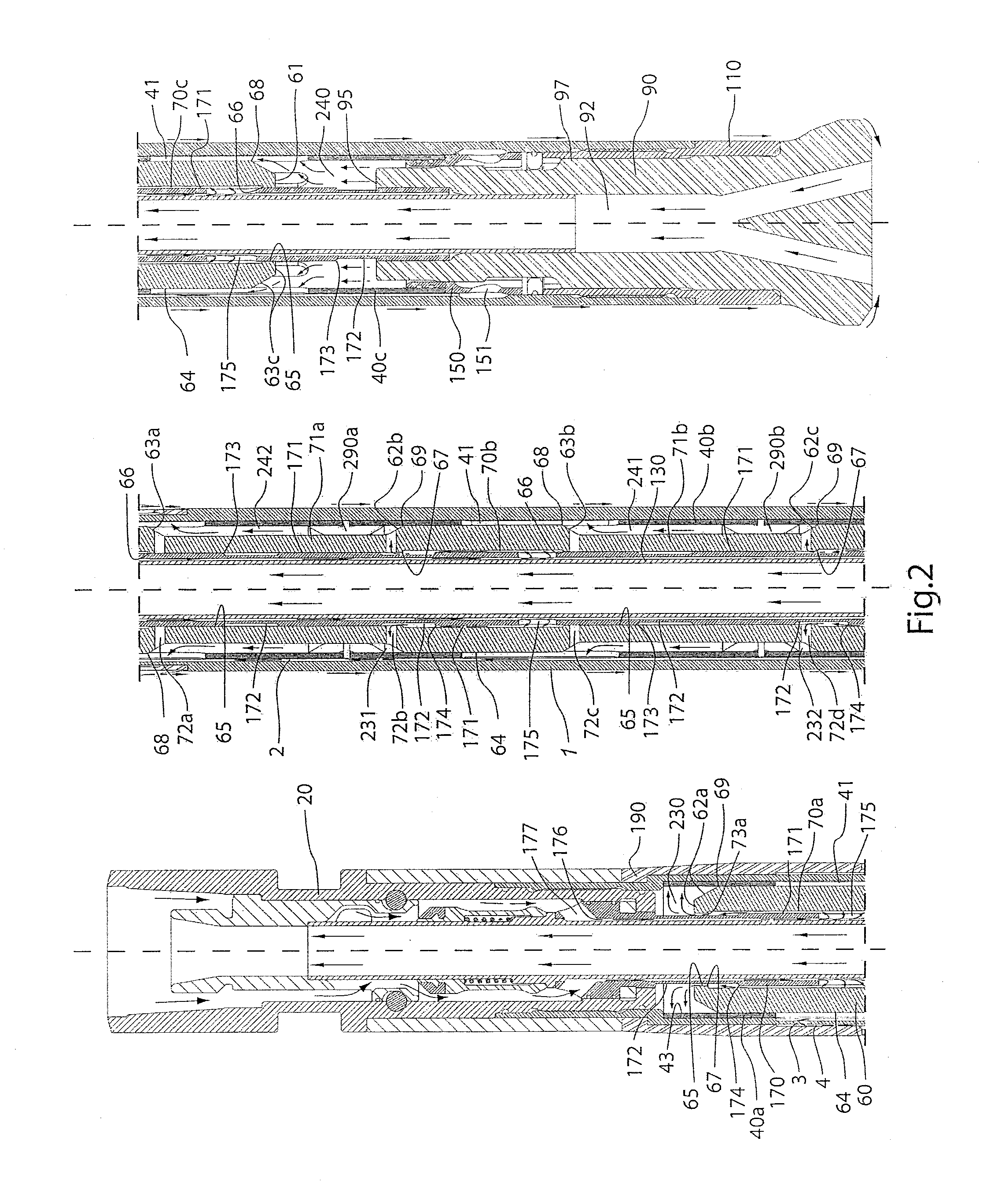
. 1 to 3)

[0036]Referring to FIGS. 1 to 3, the pressurized fluid flow system according to a first preferred embodiment of the invention comprises the following main components:

[0037]a cylindrical outer casing (1);

[0038]a rear sub (20) affixed to the rear end of said outer casing (1) for connecting the hammer to a source of pressurized fluid;

[0039]a centrally-bored piston (60) which is slidably and coaxially disposed to excert a reciprocating movement inside the outer casing (1);

[0040]a drill bit (90) which has a central bore (92) and is slidably mounted on a driver sub (110) in the front end of the hammer, wherein the drill bit (90) is aligned with the outer casing (1) by means of a drill bit guide (150) disposed inside said outer casing (1); and

[0041]a sample tube (130) coaxially disposed within the outer casing (1) and extending from the rear sub (20) to the drill bit (90), the sample tube being inserted at its front end in the central bore (92) of the drill bit (90).

[0042]As shown...


PUM


Abstract

A pressurized fluid flow system for a down the hole drill hammer has a plurality of chambers that exert work, namely one or more auxiliary drive and lifting chambers besides two main chambers located at opposite ends of the piston, the auxiliary chambers each formed around respective waists on the piston and externally delimited by respective cylinders which are arranged longitudinally in series. Two or more internal chambers filled with the pressurized fluid are defined by recesses in the inner surfaces of the piston for supplying said fluid to the work chambers, controlled in a cooperative way by the piston and a control tube coaxially arranged within a central bore of the piston. One or more discharge chambers are formed in between the outer casing and the cylinders for emptying the work chambers through discharge ports in the cylinders. Reverse and normal circulation drill hammers are provided having this system.

Description

STATE OF THE ART[0001]There are many different down the hole (DTH) drill hammers available for drilling and sample recovery in mining, civil works and in the construction of water, oil&gas and geothermal wells. These hammers are powered by pressurized fluid that is alternatively directed by different means, depending on the design of the drill hammer and type of hammer (normal circulation drill hammers are for production while reverse circulation drill hammers are for sample recovery), into a lifting chamber and a drive chamber, which are located at opposite ends of the hammer piston. As one chamber is being filled with pressurized fluid, the other is being emptied and the difference in pressure between the lifting and drive chambers causes the reciprocating movement of the piston and the impact of the same on the drill bit with each working stroke of the piston.[0002]Most of the known DTH drill hammers have only one drive chamber and one lifting chamber. In such cases, the piston h...

Claims


Application Information

Patent Timeline
Patent Type & Authority Applications(United States)
IPC IPC(8): E21B4/14
CPCE21B4/14E21B49/005
Inventor AROS, JAIME ANDRES
Owner DRILLCO TOOLS
Why Eureka
Try Eureka