Engine for hypersonic aircrafts with supersonic combustor

a combustor and hypersonic technology, applied in the direction of jet propulsion plants, gas turbine plants, ram jet engines, etc., can solve the problems of affecting the performance affecting the use of the propulsion system, and limiting the choice of fuel used, so as to reduce the addition of energy (thermal energy), the effect of efficient energy conversion

Active Publication Date: 2018-05-03
GABALDO MARCO +1
View PDF6 Cites 11 Cited by
  • Summary
  • Abstract
  • Description
  • Claims
  • Application Information

AI Technical Summary

Benefits of technology

[0110]Advantageously, in accordance with this invention, the propulsion system with the rocket powered with kerosene allows use of a poorly refined kerosene (hence less expensive) compared with that generally used. In effect, the configuration of the propulsion system according to this invention having rocket and turbojet included in the bypass duct and all three of the elements having the outlet section coinciding in the same point allows for a compensation for any possible reduced addition of energy (thermal energy) of the poorly refined kerosene, compared with the prior art, by a more efficient energy conversion (from kinetic thermal) in the energy conversion region.

Problems solved by technology

The propulsion systems for aerospace applications such as those described above have some drawbacks and limitations in their use.
A further limitation is given by the fact that supersonic steady state combustion requires a fuel suitable for that steady state, which considerably limits the choice of the fuel be used.
This limitation often forces the use of hydrogen which is the best fuel because it has, for example, a speed of propagation of the flame, an inflammability and a specific heat suitable for the operating conditions of the SCRAMJet propulsion system.
The combustion flame close to the walls of the propulsion system produces a problem of overheating of the parts themselves, for which various technologically complex measures has been adopted for achieving a sufficient insulation and / or cooling of the thermally stressed parts.
A further and different drawback relative to the pure SCRAMJet propulsion systems lies in the type of propagation of the shock waves generated inside the propulsion system which, also due to the geometrical configuration of the combustor described above, enter into direct contact with the perimeter walls of the propulsion system causing vibrations which are harmful for the propulsion system.
The combined type SCRAMJet propulsion system suffers from a limitation in terms of efficiency, and thus has a discrete propulsive effect.
This limitation is highlighted mostly during the take-off phase of the propulsion system, in general in acceleration from a fixed point, during which the rocket must operate at a steady state together with the RAMJet system, which is not yet at a steady state sufficient to cause the ideal operating conditions (typically for the values of pressure and speed of air flow at inlet).
A further drawback of this propulsion system is the maximum compression which can be achieved, which is a ratio of about 30 to 1, which is a poor value for a generic rocket engine deemed to have a good efficiency.

Method used


Image

  • Engine for hypersonic aircrafts with supersonic combustor
  • Engine for hypersonic aircrafts with supersonic combustor
  • Engine for hypersonic aircrafts with supersonic combustor

Examples


Embodiment Construction

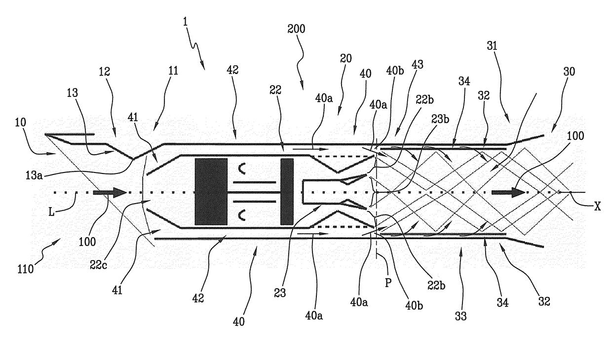
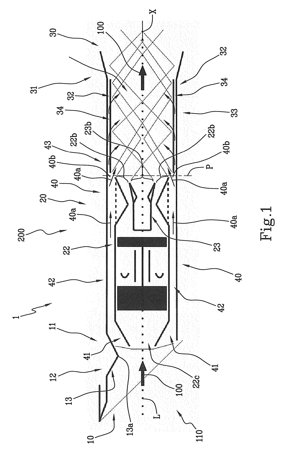
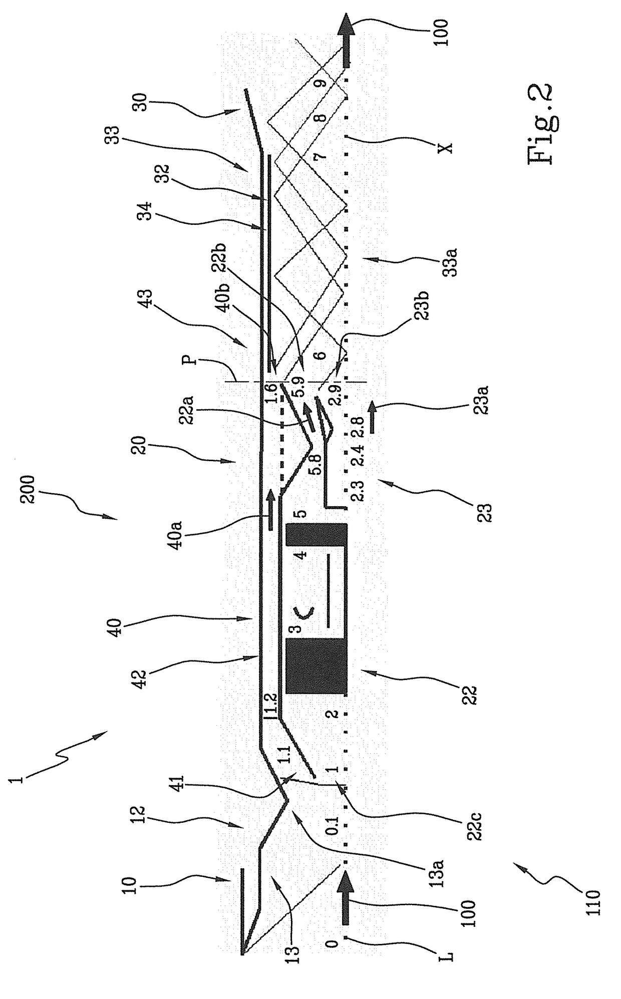
[0122]The accompanying drawings show in its entirety a propulsion system 1 for hypersonic aircraft in accordance with the inventive concept of this invention. According to a more technical and specific terminology relating to the sector of aerospace propulsion systems, this invention relates to a “rocket ignited supersonic combustion RAM jet (RISCRAM jet)”.

[0123]It should be noted that the accompanying drawings are schematic and concern specifically the propulsion system 1 according to the inventive concept of this invention; therefore, known auxiliary systems for aerospace applications such as the tanks for fuel and / or comburent, delivery pumps, hydraulic systems or systems for management of the flows 100 of a fluid 110 are not illustrated in the accompanying drawings. The operating cycle the propulsion system 1 will be described below following an introduction of the main structural elements of the propulsion system 1.

[0124]In structural terms, the propulsion system 1 according to...


PUM


Abstract

Described is a propulsion system (1) for hypersonic aircraft, having an air inlet (10) of a fluid (110), a containment duct (20) and an exhaust nozzle (30). The propulsion system (1) comprises a bypass duct (40) for a flow (100) of fluid (110), an air-breathing engine (22) and a rocket (23) configured for processing respective flows (22a, 23a) of fluid (110). The bypass duct (40), the air-breathing engine (22) and the rocket (23) are operatively associated with each other in such a way as to generate a thermodynamic-fluid interaction in a same portion of space (33) between the respective flows (40a, 22a, 23a) processed in an operating configuration of the propulsion system (1) and wherein the portion of space (33) is inside the containment duct (20).

Description

TECHNICAL FIELD[0001]This invention relates to a propulsion system for hypersonic aircraft with a supersonic combustor.[0002]More specifically, this invention relates to a propulsion system for hypersonic aircraft having a supersonic combustor which is ignited by a rocket, in other words, a propulsion system for hypersonic aircraft having a supersonic RAM combustor which is ignited by a rocket. The propulsion system according to this invention is suitable for fitting to aircraft configured to reach hypersonic steady state flight, in particular the propulsion system, according to this invention, can be used on board aircraft used in the aerospace sector for hypersonic flight.[0003]This invention relates to a propulsion system for hypersonic aircraft configured to operate from a fixed point to hypersonic steady state speed and from an altitude at sea level to an altitude which comprises the terrestrial exosphere.Background[0004]In the prior state of the art there are various configura...

Claims


Application Information

Patent Timeline
Patent Type & Authority Applications(United States)
IPC IPC(8): F02K7/18F02C3/24F02C7/042F02K1/06F02K3/02F02K3/08F02K7/14
CPCF02K7/18F02C3/24F02C7/042F02K1/06F02K3/02F02K3/08F02K7/14F05D2220/10F05D2250/311
Inventor GABALDO, MARCOMAUTONE BARROS, JOSE EDUARDO
Owner GABALDO MARCO
Why Eureka
Try Eureka