Optical detecting method and device for back drilling depth

An optical detection and depth technology, applied in the direction of using optical devices, measuring devices, instruments, etc., can solve the problems of detection result distortion, product waste, damage to work boards, etc., to reduce the use of auxiliary materials, improve detection efficiency, and facilitate positioning Detection effect

Active Publication Date: 2019-03-29
ANHUI SUN CREATE ELECTRONICS
View PDF5 Cites 7 Cited by
  • Summary
  • Abstract
  • Description
  • Claims
  • Application Information

AI Technical Summary

Problems solved by technology

[0002] The traditional metallographic section method is used to detect the depth of back drilling. This method must destroy the working board. If the internal product is used for detection, it will cause waste of products; if the external test hole is used for detection, it may cause The detection result is distorted
At the same time, this method must be ground on a special grinding device when slicing, resulting in waste of materials such as sandpaper, water, resin powder, and quartz powder, and each slice can only detect local back drilling.
[0003] Therefore, the traditional detection of back-drilling depth using metallographic slices is time-consuming and labor-intensive and cannot be detected globally.

Method used


Image

  • Optical detecting method and device for back drilling depth
  • Optical detecting method and device for back drilling depth
  • Optical detecting method and device for back drilling depth

Examples


Embodiment Construction

[0029] The technical solutions in the embodiments of the present invention will be clearly and completely described below with reference to the accompanying drawings in the embodiments of the present invention. Obviously, the described embodiments are only a part of the embodiments of the present invention, but not all of the embodiments. Based on the embodiments of the present invention, all other embodiments obtained by those of ordinary skill in the art without creative efforts shall fall within the protection scope of the present invention.

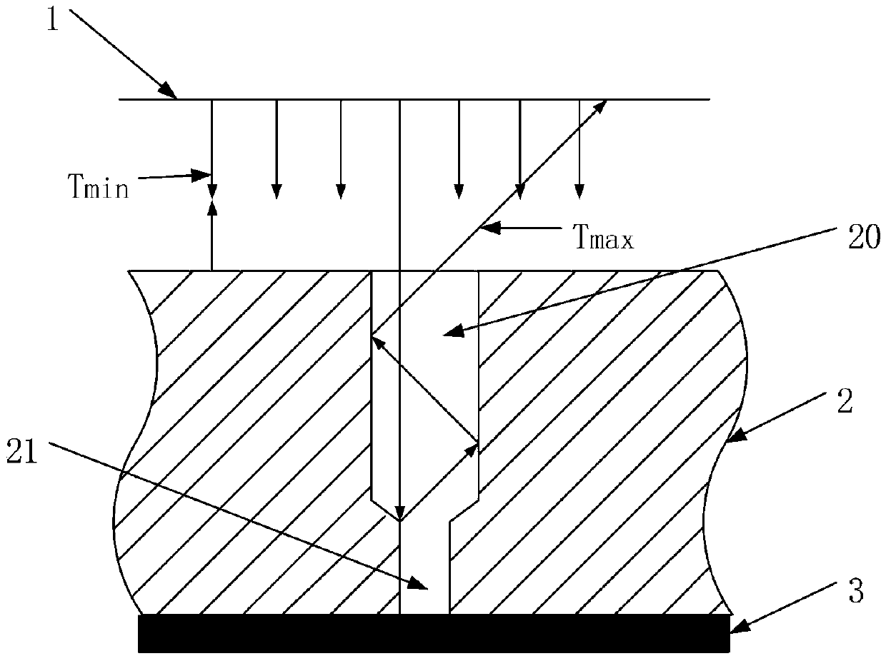
[0030] Depend on image 3 As shown, an optical detection device for the depth of back drilling includes: a detection instrument 1, a work plate 2, and a light-absorbing component 3;

[0031] Wherein, the detection instrument 1 is a pulse transceiver integrating transmitting and receiving, and is used for receiving and transmitting beam pulses;

[0032] The detection instrument 1 is provided with a positioning member at the beam pulse...


PUM


Abstract

The invention relates to the field of detecting back drilling depth of a PCB, in particular to an optical detecting method and device for a back drilling depth. The method comprises the steps of: vertically transmitting a plurality of light beam pulses to a back drilling surface of a workbench at the same moment by a detection instrument, and setting the starting emitting time of the light beam pulses as 0s; receiving the reflected light beam pulses of each light beam pulse by the detection instrument, and recording the receiving time of each reflected light beam pulse, wherein the maximum value of the receiving time is Tmax, and the minimum value of the receiving time is Tmin; and calculating the depth H of the back drilling hole according to the maximum value Tmax and the minimum Tmin inthe receiving time of each reflected light beam pulse, the transmission speed V of the light beam pulses and the angle [theta] of a drilling needle of the back drilling hole. The optical detecting method effectively improves the detection efficiency and rapidly detects the global back drilling situation on the premise without damaging of the workbench; and moreover, the usage of secondary materials is reduced and the purpose of energy-saving and cost-reducing is achieved.

Description

technical field [0001] The invention relates to the field of detection of the back-drilling depth of a PCB, in particular to an optical detection method and a detection device of the back-drilling depth. Background technique [0002] The traditional metallographic slicing method is used to detect the depth of back drilling. This method must destroy the work board. If the internal product is used for detection, it will cause waste of products; if the external test hole is used for detection, it may cause The detection result is distorted. At the same time, this method must be ground on special grinding equipment when slicing, resulting in waste of materials such as sandpaper, water, resin powder and quartz powder, and each slice can only detect local back drilling. [0003] Therefore, the traditional back-drilling depth detection using metallographic slices has the problems of time-consuming and labor-intensive and unable to detect globally. SUMMARY OF THE INVENTION [00...

Claims


Application Information

Patent Timeline
Patent Type & Authority Applications(China)
IPC IPC(8): G01B11/22
CPCG01B11/22
Inventor 牛顺义沈岳峰朱忠翰管美章崔良端陈彦青戴银海彭腾范晓春邓建李燚
Owner ANHUI SUN CREATE ELECTRONICS
Why Eureka
Try Eureka