Ultrasonic gas meter

A gas meter and ultrasonic technology, applied in the direction of measuring devices, instruments, measuring flow/mass flow, etc., can solve the problems of gas equipment unable to use gas, pipeline blockage, and inability to discharge, so as to ensure effective gas chamber space and reduce pressure Loss value, effect of preventing inaccurate measurement

Pending Publication Date: 2019-03-29
上海埃科燃气测控设备有限公司
View PDF0 Cites 2 Cited by
  • Summary
  • Abstract
  • Description
  • Claims
  • Application Information

AI Technical Summary

Problems solved by technology

[0004] If there is water in the gas medium or in the pipeline, the structure of the traditional ultrasonic gas meter will cause water to accumulate for a long time after entering the air inlet and cannot be discharged.
Once the surface of the transducer (ultrasonic probe) on the metering module is stained with water, or water enters the air passage of the metering module, it will cause inaccurate metering
[0005] In the traditional structure, the pipes are blocked due to too much accumulated water, and the gas equipment behind the gas meter cannot use gas.
[0006] Under normal circumstances, most of this ultrasonic gas meter is used in gas trade settlement. This situation will also become a way for some low-quality users to maliciously destroy (artificially pour water into it), so as to achieve the purpose of illegal gas theft and cause a lot of damage. Economic losses

Method used


Image

  • Ultrasonic gas meter
  • Ultrasonic gas meter
  • Ultrasonic gas meter

Examples


Embodiment 1

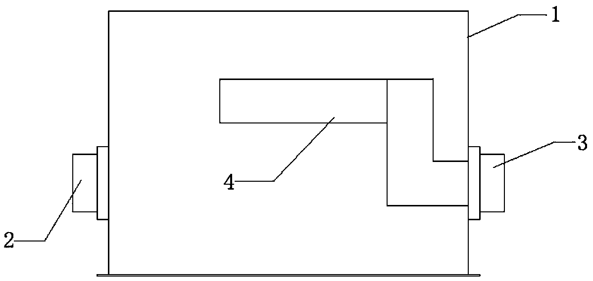
[0027] Such as figure 1 Shown is a schematic structural diagram of an ultrasonic gas meter, which includes a housing 1 , an air inlet 2 , an air outlet 3 , and a metering module 4 . The air inlet 2 and the air outlet 3 are respectively connected to existing gas pipelines.

[0028] The air inlet 2 is set on the side of the housing 1. The location of the air inlet 2 in this device breaks the inherent thinking of the structure of the air inlet 2 and the air outlet 3 in the structure of the traditional ultrasonic gas meter, and the air inlet 2 is set on the The side of the housing 1 can effectively prevent the water in the pipeline from flowing into the housing 1 from the air inlet 2, and at the same time, prevent water or other liquids from being artificially poured into the housing 1 from the air inlet 2, which will damage the metering Module 4 measurements.

[0029] The metering module 4 is arranged in the casing 1, and the metering module 4 is composed of a transducer, and t...

Embodiment 2

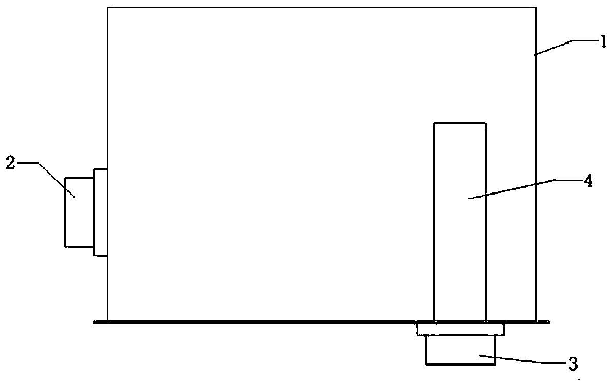
[0037] Such as figure 2 Shown: is an ultrasonic gas meter including a housing 1, a metering module 4, the metering module 4 is set in the housing 1, the housing 1 is provided with an air inlet 2 and an air outlet 3, an air inlet 2 and an air outlet 3 Connect the existing gas pipelines respectively. The metering module 4 is arranged in the casing 1, and the metering module 4 is composed of a transducer, and the transducer is composed of one or more sets of ultrasonic probes and air passages. After the gas enters the casing 1 from the air inlet 2, it flows A stabilized air chamber is formed inside, and then the air is fed from the inlet port of the metering module 4, and the accurate flow rate can be obtained through the metering module 4. It is discharged from the gas outlet of the metering module 4 to the gas outlet 3.

[0038] The air inlet 2 is set on the side of the housing 1, and the location of the air inlet 2 is different from the traditional air inlet 2, breaking the...

Embodiment 3

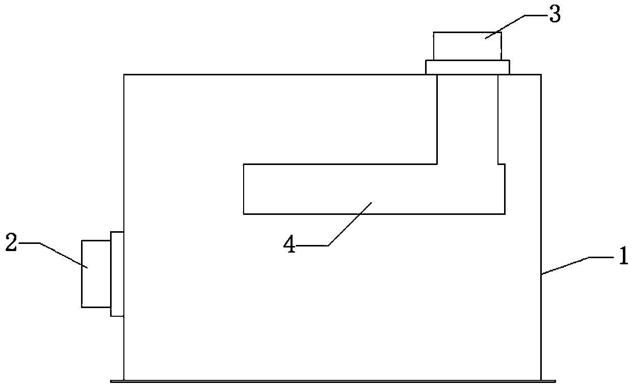
[0043] Such as image 3 As shown, an ultrasonic gas meter includes a housing 1 and a metering module 4, the metering module 4 is arranged in the housing 1, and the housing 1 is provided with an air inlet 2 and an air outlet 3, and an air inlet 2 and an air outlet 3 Connect the existing gas pipelines respectively.

[0044] The metering module 4 is composed of a transducer, and the transducer is composed of one or more sets of ultrasonic probes and air passages. After the gas enters the housing 1 from the air inlet 2, a stable pressure gas chamber is formed in the housing 1, and then The air is fed through the air inlet of the metering module 4 , and an accurate flow rate can be obtained through the metering module 4 . The air outlet of the metering module 4 is connected to the air outlet 3 of the casing 1 through an air outlet connecting pipe. The gas is then discharged from the gas outlet of the metering module 4 to the gas outlet 3 .

[0045] The air inlet 2 is set on the s...


PUM


Abstract

The invention provides an ultrasonic gas meter. The ultrasonic gas meter comprises a shell and a metering module, wherein the metering module is arranged in the shell; a gas inlet and a gas outlet areformed in the shell; the gas outlet end of the metering module is connected with the gas outlet; and the gas inlet is formed in a side surface of the shell. The structural arrangement of the gas meter breaks through the fixed thinking of the structural design of a traditional ultrasonic gas meter; and by changing the arrangement position of the gas inlet, water is prevented from being brought into the shell through the gas inlet.

Description

technical field [0001] The invention relates to the field of gas measurement, in particular to an ultrasonic gas meter. Background technique [0002] For traditional ultrasonic gas meters, the air inlet and outlet are at the top of the housing, and there is a metering module inside the housing. In the conventional structure, the air inlet of the housing and the air inlet of the metering module are open. [0003] The big flaws of traditional ultrasonic gas meters are: [0004] If there is water in the gas medium or in the pipeline, the structure of the traditional ultrasonic gas meter will cause water to accumulate for a long time after entering the air inlet and cannot be discharged. Once the surface of the transducer (ultrasonic probe) on the metering module is stained with water, or water enters the air passage of the metering module, inaccurate metering will result. [0005] In the traditional structure, the pipes are blocked due to excessive water accumulation, which ...

Claims


Application Information

Patent Timeline
Patent Type & Authority Applications(China)
IPC IPC(8): G01F1/66
CPCG01F1/662
Inventor 赵建新卢小林陆永明张吉忠董智计青张东伟
Owner 上海埃科燃气测控设备有限公司
Why Eureka
Try Eureka