
Device and method for comprehensively utilizing construction waste

A construction waste and directly below technology, which is applied in the field of comprehensive utilization of construction waste devices, can solve the problems of time-consuming, labor-intensive, low recycling efficiency, etc., and achieve the effect of ensuring normal power on

Active Publication Date: 2020-04-17
中欧国际建工集团有限公司
View PDF10 Cites 8 Cited by
  • Summary
  • Abstract
  • Description
  • Claims
  • Application Information

AI Technical Summary

Problems solved by technology

[0004] However, after crushing, the construction waste is usually separated manually to recycle metals such as scrap steel bars and scrap iron wires; it is time-consuming and laborious, and the recycling efficiency is low

Method used


Image

  • Device and method for comprehensively utilizing construction waste
  • Device and method for comprehensively utilizing construction waste
  • Device and method for comprehensively utilizing construction waste

Examples


Embodiment 1

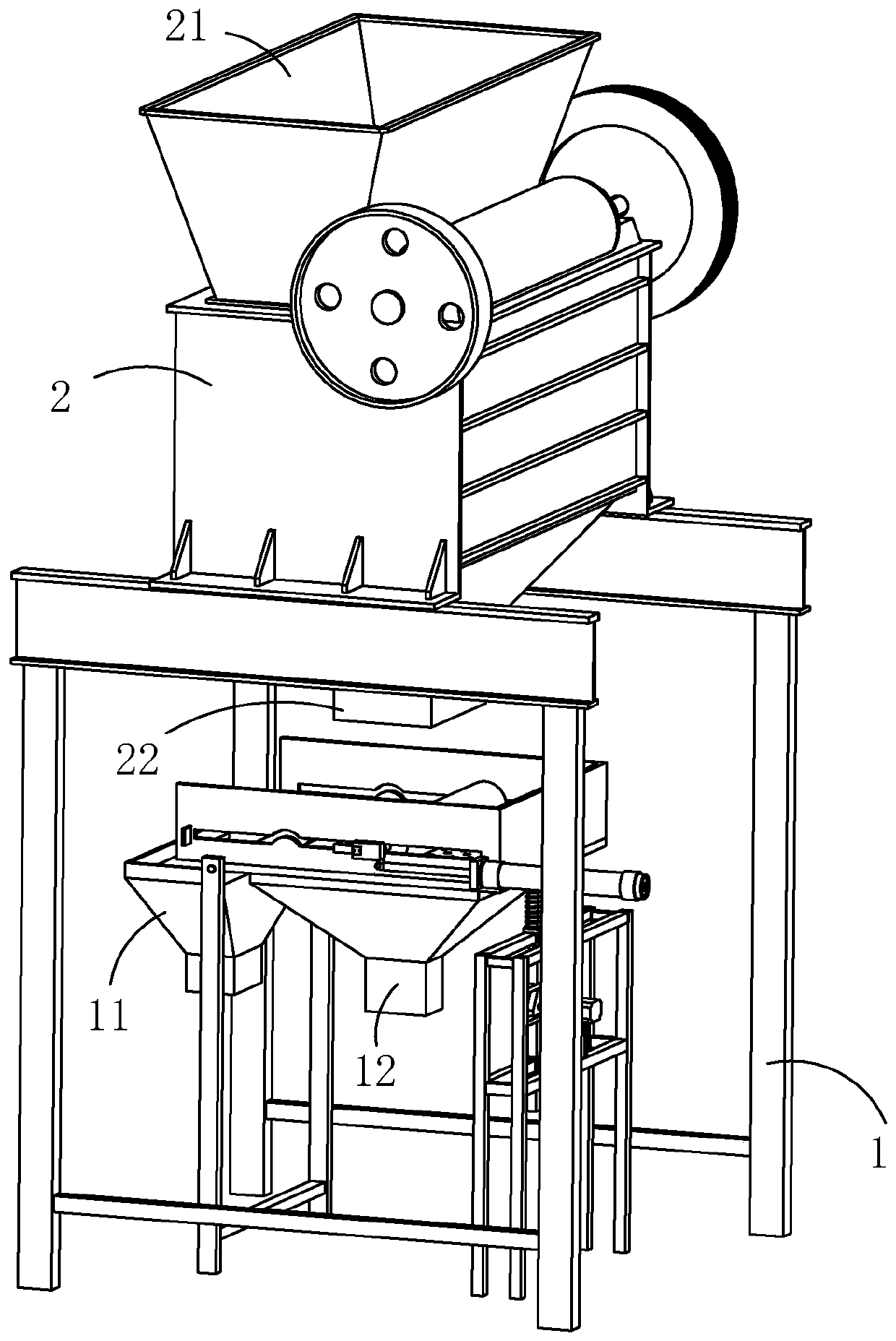
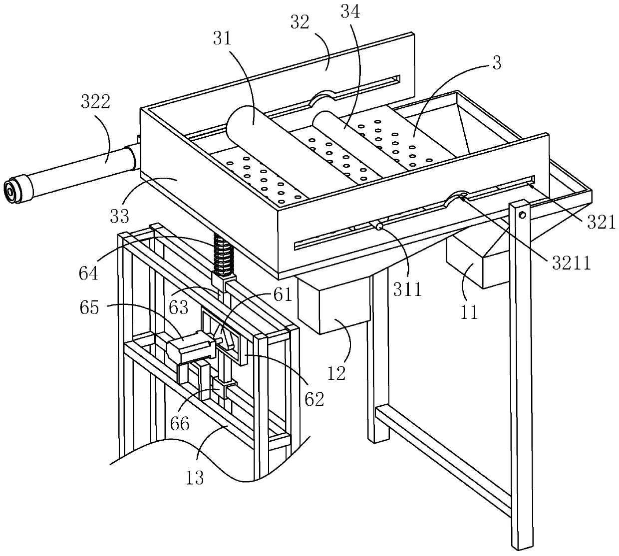
[0043] Such as figure 1 , 2 As shown, a device for comprehensive utilization of construction waste includes a frame 1 on which a pulverizer 2 for pulverizing construction waste is arranged. The pulverizer 2 includes a feed port 21 and a discharge port 22 . A screening plate 3 is arranged on the frame 1, and the screening plate 3 is made of a mesh plate, and the screening plate 3 is located directly below the discharge port 22.

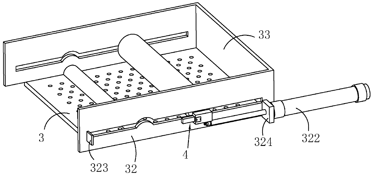
[0044] Such as figure 1 , 2 As shown, a pressing roller 31 is arranged on the screening plate 3, an electromagnet (not shown in the figure) is arranged inside the pressing roller 31, a recovery bucket 11 is arranged on one side of the screening plate 3, and a There is a discharge hopper 12; the frame 1 is provided with a driving member for driving the pressure roller 31 to move closer to or away from the recovery hopper 11, and the driving member is an air cylinder 322.

[0045] Such as figure 1 , 2 As shown, the frame 1 is provided with a driving ...

Embodiment 2

[0059] A method for comprehensively utilizing construction waste, comprising the following steps:

[0060] S1. Sorting construction waste and removing plastic waste;

[0061] S2. Put the construction waste into the shredder 2 for crushing, the scrap iron is discharged through the recovery hopper 11, and other construction waste is discharged through the discharge hopper 12;

[0062] S3. The construction waste discharged from the discharge hopper 12 is used to make building materials such as building blocks, paving bricks, and lattice bricks.

[0063] The construction waste after preliminary classification is crushed by the shredder 2, and the crushed construction waste is discharged through the discharge hopper 12, and the scrap iron is discharged through the recovery hopper 11, which is convenient for recycling scrap iron; while other construction waste is used to make masonry Blocks, paving bricks, checkered bricks and other building material products to improve resource ut...


PUM


Abstract

The invention relates to a device and method for comprehensively utilizing construction waste, and belongs to the technical field of construction waste disposal. The device comprises a machine frame.A pulverizing machine for pulverizing the construction waste is arranged on the machine frame. The pulverizing machine comprises a feed port and a discharge port. A screening plate is arranged on themachine frame and located under the discharge port. A pressing roller is arranged on the screening plate. An electromagnet is arranged in the pressing roller. A recovery hopper is arranged on one sideof the screening plate. A discharge hopper is arranged under the screening plate. A driving piece for driving the pressing roller to get close to or away from the recovery hopper is arranged on the machine frame. The driving piece drives the pressing roller to roll on the screening plate so as to further crush the construction waste; scrap iron in the construction waste is attracted to the surface of the pressing roller through the electromagnet, and other construction waste falls into the discharge hopper through the screening plate; and the aim of sorting out the scrap iron is realized, andthe scrap iron can be conveniently recovered.

Description

technical field [0001] The invention relates to the technical field of construction waste treatment, in particular to a device and method for comprehensively utilizing construction waste. Background technique [0002] Construction waste refers to the dregs, spoils, waste materials, silt and other wastes generated during the construction, laying or demolition, and repair of various buildings, structures, and pipe networks by construction units or individuals. The recycling of garbage and municipal garbage resources can greatly reduce the landfill area of ​​garbage and reduce environmental pollution. [0003] At present, the processing and recycling of construction waste usually needs to be crushed and separated, and then metals such as waste steel bars, waste iron wires, waste wires and various scrap steel accessories are recovered, and the crushed construction waste is used for masonry mortar and plastering Mortar, concrete cushion, etc., or used to make building blocks, pa...

Claims


Application Information

Patent Timeline
Patent Type & Authority Applications(China)
IPC IPC(8): B09B3/00B02C21/00B02C4/00B02C4/42B02C23/16B03C1/02B07B1/34B07B1/42B07B1/46
CPCB02C4/00B02C4/42B02C21/00B02C23/16B02C2023/165B02C2201/06B03C1/02B07B1/343B07B1/42B07B1/46B09B3/00Y02W30/58
Inventor 王永存王衡刘婷
Owner 中欧国际建工集团有限公司
Learn More