
Fluorescence intensity ratio temperature measuring method based on double-wavelength light source

A fluorescence intensity ratio and fluorescence intensity technology, which is applied in the field of fluorescence intensity ratio temperature measurement, can solve problems such as relative sensitivity attenuation, and achieve the effect of improving relative sensitivity and high temperature measurement sensitivity.

Active Publication Date: 2019-03-29
HARBIN INST OF TECH
View PDF6 Cites 6 Cited by
  • Summary
  • Abstract
  • Description
  • Claims
  • Application Information

AI Technical Summary

Problems solved by technology

[0004] The purpose of the present invention is to solve the problem that the relative sensitivity of the existing rare earth ion fluorescence intensity temperature measurement technology will be rapidly attenuated in the higher temperature range, and to provide a fluorescence intensity ratio temperature measurement method based on a dual-wavelength light source

Method used


Image

  • Fluorescence intensity ratio temperature measuring method based on double-wavelength light source
  • Fluorescence intensity ratio temperature measuring method based on double-wavelength light source
  • Fluorescence intensity ratio temperature measuring method based on double-wavelength light source

Examples


specific Embodiment approach 1

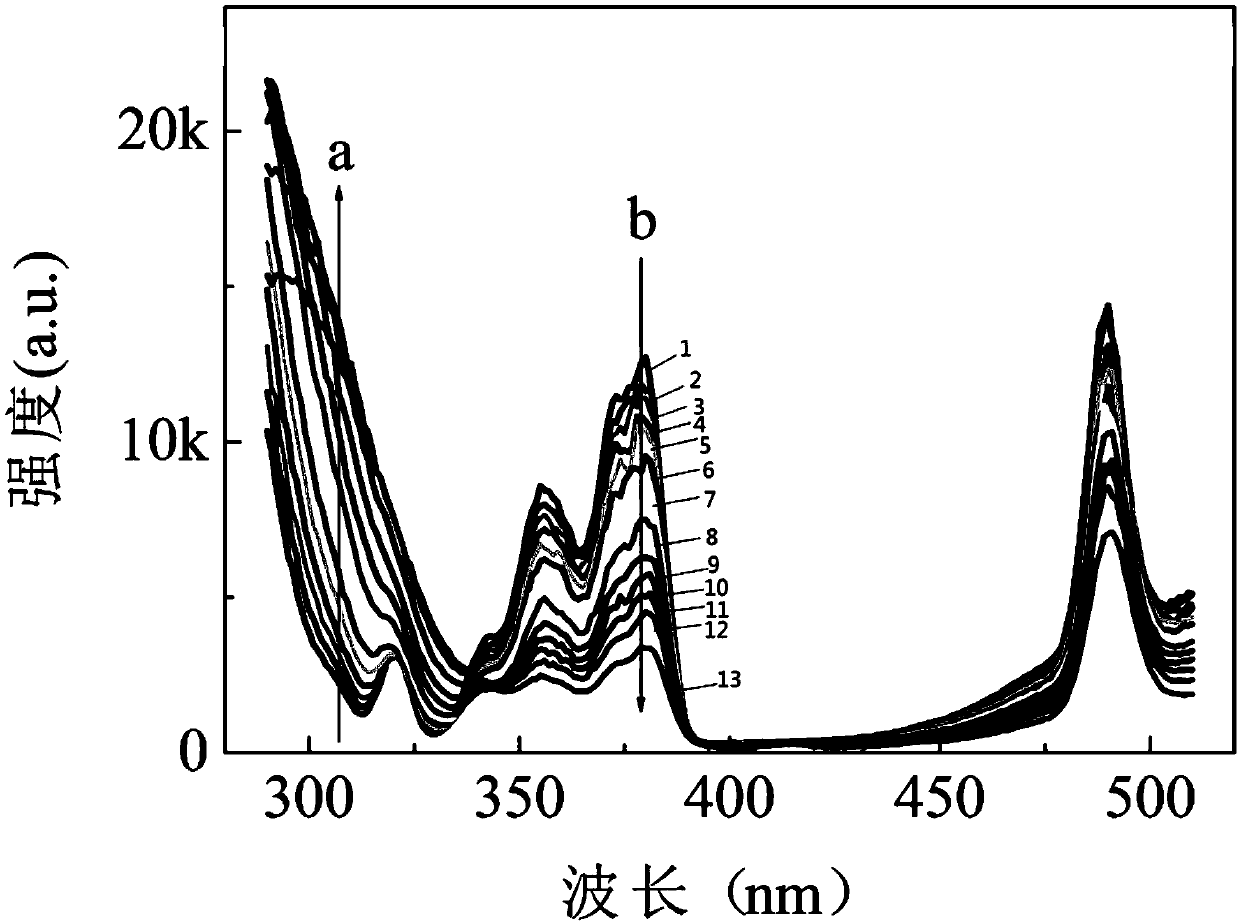
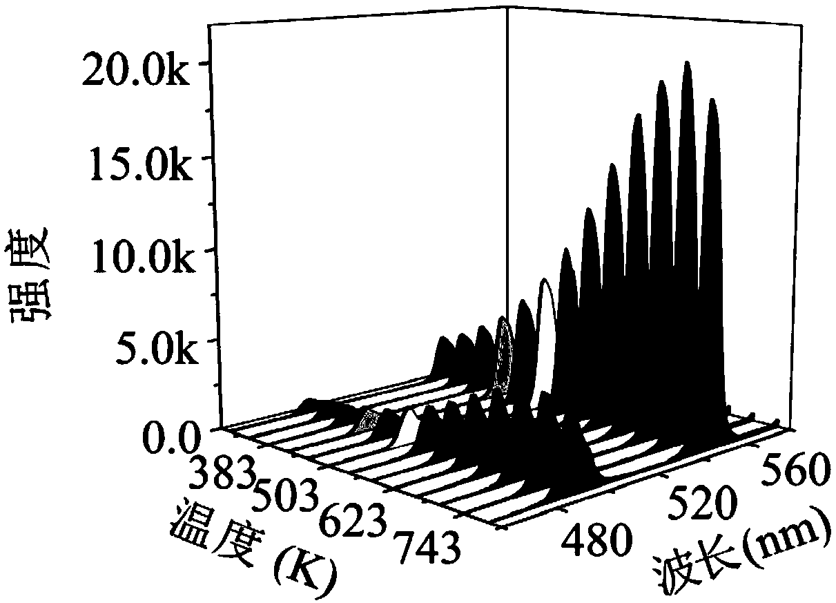
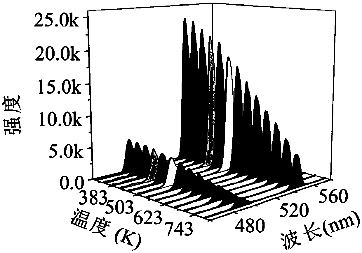
[0014] Specific Embodiment 1: In this embodiment, a method for measuring temperature based on the fluorescence intensity ratio of a dual-wavelength light source is carried out in the following steps: (1) prepare CaWO 4 :Tb 3+ temperature-sensitive material, and place the material on a heating table, use a 150W xenon lamp as an excitation light source, and use a grating spectrometer as a spectrometer; (2) the heating table is heated in the temperature range from 303K to 783K, and the temperature interval of each calibration temperature 40K, and then irradiate the sample with a light source with a center wavelength of 310nm of a xenon lamp after spectrometry, and record the rare earth Tb 3+ The intensity of green fluorescence emitted by ions is recorded as fluorescence intensity A; then the sample is irradiated with a light source with a center wavelength of 378nm of a xenon lamp after spectrometry, and the rare earth Tb 3+ The intensity of green fluorescence emitted by ions is...

specific Embodiment approach 2

[0018] Specific embodiment two: the difference between this embodiment and specific embodiment one is: CaWO4:Tb in step (1) 3+ The preparation method of the temperature-sensitive material is a high-temperature solid-phase method, the calcination temperature is 1150° C., and the holding time is 6 hours. Others are the same as in the first embodiment.

specific Embodiment approach 3

[0019] Specific embodiment three: the difference between this embodiment and specific embodiment one or two is: CaWO4:Tb prepared in step (1) 3+ Tb in temperature sensitive materials 3+ The molar percentage is 5%. Others are the same as in the first or second embodiment.


PUM


Abstract

The invention relates to a fluorescence intensity ratio temperature measuring method based on a double-wavelength light source. The invention aims to settle a problem of quick relative sensitivity reduction in a relatively high temperature interval in existing rare earth ion fluorescent intensity temperature measuring technology. According to the method, in a temperature range of 303-783K, the intensity ratio of green fluorescent light which is emitted from rare earth Tb3+ ion after light splitting of xenon lamp through excitation of a light source with wavelengths of 310nm and 378nm and has acentral wavelength of 545nm. The function relation between the intensity ratio and temperature is a temperature measuring curve. The function relation can be used for measuring the temperature in anunknown environment. Based on the method, temperature response with higher sensitivity can be obtained in a relatively high temperature range, and the sensitivity is remarkably higher than the sensitivity which can be realized in current routine optical methods. The fluorescence intensity ratio temperature measuring method is applied to the field of fluorescence intensity ratio temperature measurement.

Description

technical field [0001] The invention relates to a fluorescence intensity ratio temperature measurement method based on a dual-wavelength light source. Background technique [0002] The importance of temperature is self-evident, so how to obtain this parameter accurately and quickly becomes extremely critical. With the development of science and technology, temperature measurement methods are becoming more and more diverse. Among them, optical temperature measurement methods have become more and more important, because this type of method can be applied in non-contact occasions, and the response time is very short, so It greatly expands the application scenarios of temperature measurement. [0003] Among the many optical temperature measurement methods, the fluorescence intensity ratio temperature measurement technology based on lanthanides has received extensive attention, because it has the following advantages: (1) Because it uses the ratio method to measure temperature, ...

Claims


Application Information

Patent Timeline
Patent Type & Authority Applications(China)
IPC IPC(8): G01K11/00
CPCG01K11/00
Inventor 张治国李磊朋秦峰
Owner HARBIN INST OF TECH
Learn More