Fluorescence intensity ratio temperature measurement method based on charge migration band edge abnormal thermal quenching

A fluorescence intensity ratio and charge transfer technology, which is applied in the field of fluorescence intensity ratio temperature measurement, can solve the problems of decoupling, thermal coupling energy level difference, etc.

Active Publication Date: 2020-11-17
CHONGQING UNIV OF POSTS & TELECOMM
View PDF9 Cites 0 Cited by
  • Summary
  • Abstract
  • Description
  • Claims
  • Application Information

AI Technical Summary

Problems solved by technology

This TCEL-based technique is limited by the thermal coupling energy level difference, which can cause "uncoupling" if the energy difference is slightly larger, so this technology has inherent limitations to the improvement of sensitivity

Method used


Image

  • Fluorescence intensity ratio temperature measurement method based on charge migration band edge abnormal thermal quenching
  • Fluorescence intensity ratio temperature measurement method based on charge migration band edge abnormal thermal quenching
  • Fluorescence intensity ratio temperature measurement method based on charge migration band edge abnormal thermal quenching

Examples


specific Embodiment approach 1

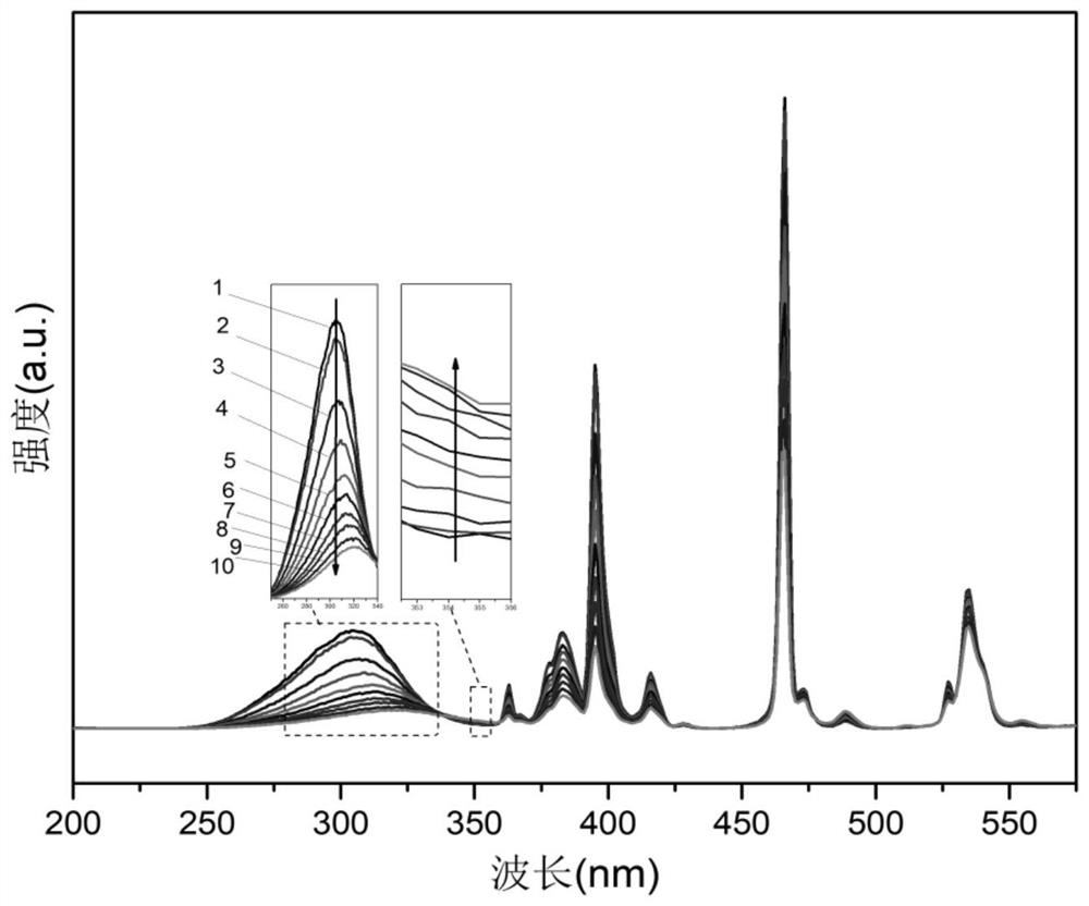
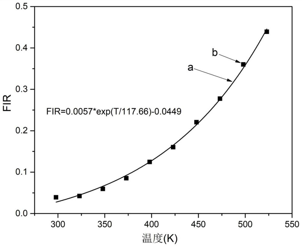
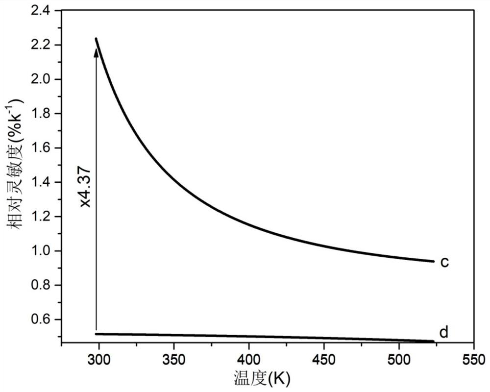
[0025] Specific embodiment one: a kind of fluorescence intensity ratio thermometry method based on anomalous thermal quenching at the edge of the charge transfer band is carried out according to the following steps: (1) prepare NaLaCaWO 6 :Eu 3+temperature-sensitive material, and put the material in the high-temperature sample chamber of the fluorescence spectrometer FLS920, with a 450W xenon lamp as the excitation light source, and the temperature control platform adopts the TAP-02 (Orient-KOJI) that is matched with the spectrometer; (2) The temperature control platform is at 298 Heating to the temperature range of 523K, the temperature interval of each calibration temperature is 25K, the monitoring wavelength is set to 615nm, and the intensity of the sample excitation spectrum at 308nm and the intensity at the edge of the charge transfer band at 354nm are recorded. Integrate the fluorescence intensity band at 308nm of the excitation spectrum and the fluorescence intensity at...

specific Embodiment approach 2

[0029] Specific embodiment two: the difference between this embodiment and specific embodiment one is: NaLaCaWO in step (1) 6 :Eu 3+ The preparation method of the temperature-sensitive material is a high-temperature solid-phase method, the calcination temperature is 1250° C., and the holding time is 6 hours. Others are the same as in the first embodiment.

specific Embodiment approach 3

[0030] Specific embodiment three: the difference between this embodiment and specific embodiment one or two is: the NaLaCaWO prepared in step (1) 6 :Eu 3+ Eu in temperature sensitive materials 3+ The mole percentage is 30%. Others are the same as in the first or second embodiment.


PUM


Abstract

The invention discloses a fluorescence intensity ratio temperature measurement method based on charge migration band edge abnormal thermal quenching, and relates to a fluorescence intensity ratio temperature measurement method based on charge migration band abnormal thermal quenching. The invention aims to solve the problem that the traditional temperature measurement sensitivity based on the rareearth ion thermal coupling energy level fluorescence intensity ratio is lower. The method comprises the following steps that: (1) Eu<3+>: NaLaCaWO6 is taken as a temperature sensing material; and (2)in a temperature interval from 298 K to 528 K, the fluorescence intensity ratio I308 / I354 is gradually increased along with the rise of the temperature and has a monotonous function relationship withthe temperature T, the function relationship between the intensity ratio and the temperature is a temperature measurement curve, and the purpose of temperature measurement can be achieved by monitoring the fluorescence intensity ratio. The temperature measurement sensitivity obtained by the temperature measurement method disclosed by the invention can reach 2.23% K1 at 298 K. Compared with a traditional temperature measurement method, the method has the advantage that the sensitivity at 298 K is improved by 4.37 times. The temperature measuring method provided by the invention has high sensitivity. The method is applied to the field of rare earth fluorescence temperature measurement.

Description

technical field [0001] The invention belongs to the field of temperature measurement methods, in particular to the technology of fluorescence intensity ratio temperature measurement methods. Background technique [0002] The importance of temperature to scientific research and industrial production is self-evident. The fluorescence intensity ratio temperature measurement method based on rare earth materials quantitatively analyzes the dependence of the fluorescence performance of the sample on the temperature through the ratio of the integral intensity of the emission peak at different temperatures. The detection of temperature by this temperature sensing technology does not depend on the concentration of the luminescent center. , shape, excitation light source, fluorescence detector stability, and has the advantages of real-time detection and rapid temperature distribution imaging, etc., can achieve non-contact, long-term, stable and accurate temperature measurement. [00...

Claims


Application Information

Patent Timeline
IPC IPC(8): G01K11/20
CPCG01K11/20
Inventor 周贤菊李思雨李丽相国涛江莎曹中民谢广新
Owner CHONGQING UNIV OF POSTS & TELECOMM
Why Eureka
Try Eureka