Test method and system for simulating bonding property between rock-soil and anchor under formation pressure

A bonding performance and testing system technology, applied in the direction of measuring devices, mechanical devices, instruments, etc., can solve the problems of unable to make the original state of rock and soil compressive stress state, uneven radial deformation of samples, and affecting test results, etc. Achieve high test efficiency, uniform radial deformation, and simple operation

Active Publication Date: 2019-03-29
HUNAN UNIV
View PDF8 Cites 18 Cited by
  • Summary
  • Abstract
  • Description
  • Claims
  • Application Information

AI Technical Summary

Problems solved by technology

A cylindrical loading air bag is set on the outside of the sample, which can pressurize the side of the sample, but not the end of the sample, so that the undisturbed rock and soil cannot be compressed and restored to the initial formation stress state; in addition, the sample The two ends of the sample are in direct contact with the upper and lower cover plates, resulting in a friction effect at both ends of the sample, which in turn makes the radial deformation of the sample uneven
[0006] The Chinese invention patent "A Rock Side Friction Test Device and Method with Controllable Confining Pressure (Publication No.: CN105547841 A, Application Publication Date 2016.05.04)" discloses a rock side friction tester usin...

Method used


Image

  • Test method and system for simulating bonding property between rock-soil and anchor under formation pressure
  • Test method and system for simulating bonding property between rock-soil and anchor under formation pressure
  • Test method and system for simulating bonding property between rock-soil and anchor under formation pressure

Examples


Embodiment Construction

[0053] The embodiments of the present invention will be further described below in conjunction with the drawings and examples. It should be noted that the embodiments do not limit the scope of protection claimed by the present invention.

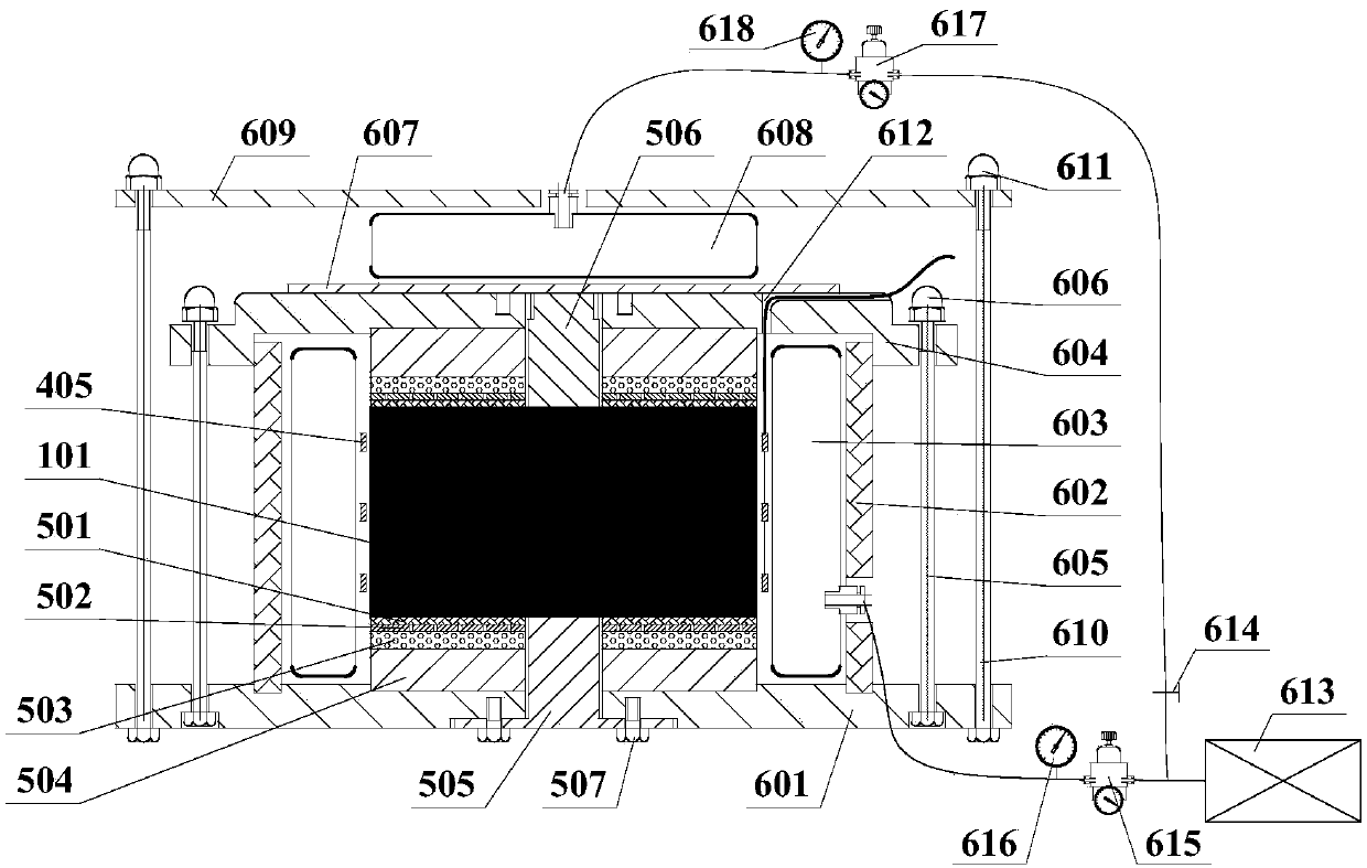
[0054] A system for testing the bonding performance of an undisturbed rock-soil mass and an anchor body under simulated formation pressure mainly includes a measuring device, a sample fixing device, a formation pressure simulating device and a pressure grouting device.

[0055] Such as figure 1 As shown, the upper and lower surfaces of the sample are sequentially installed with silica gel gasket 501, perforated steel sheet 502, permeable stone 503 and backing plate 504; The circular groove of the plate 504 displacement, the sleeve 602 is not in contact with the middle cover plate 604, the top plug 506 is placed in the upper cavity 509 on the top of the soil / rock block 101 and is flush with the top surface of the middle cover plate 604, and ...


PUM

PropertyMeasurementUnit
Thicknessaaaaaaaaaa
Elastic modulusaaaaaaaaaa

Abstract

The invention discloses a test method and system for simulating bonding property between undisturbed rock-soil and an anchor under formation pressure. The test system comprises: a measuring device, asample fixing device, a formation pressure simulating device, and a pressure grouting device. Pressure bladders are mounted on the side surface and the top surface of a sample, respectively. A radialdeformation gauge is mounted on the outside of the sample. One ends of a grouting plug and a stopping plug are topless conical shapes. An exhaust valve is provided on the bottom of a support beam. Thetest system can perform pressure grouting on the sample and monitor the radial deformation. The dual pressure bladder can apply pressure to the lateral and vertical directions of the sample to simulate formation pressure. The silicone gasket and the perforated steel sheet are placed on the upper surface and below surface of the sample to eliminate the end friction effect. The rock/soil was compressed and restored to the initial formation pressure to limit the vertical deformation of the sample. The stress state, the stress path, and the preparation process of the sample are consistent with the actual situation of the anchor, which is suitable for the test of the bonding property between the rock-soil and the anchor under various working conditions.

Description

technical field [0001] The invention relates to a bolt testing technology often used in engineering such as slopes, foundation pits, tunnels, mines, and traffic, and in particular to a testing system and testing method for the bonding performance of undisturbed rock-soil bodies and anchoring bodies under the action of simulated formation pressure. Background technique [0002] Bolt support technology is widely used in geotechnical engineering such as slopes, foundation pits, tunnels, mines, etc. due to its advantages of convenient construction and low cost. In engineering, the bearing capacity of the bolt is mostly evaluated according to the results of the field test. Although the field test can reflect the actual bearing characteristics of the bolt, it has high cost, long test cycle time, affects the construction period, and cannot simulate various working conditions (such as heavy rain Working conditions, dry and wet cycle conditions, etc.) and other shortcomings. [0003...

Claims


Application Information

Patent Timeline
IPC IPC(8): G01N19/04
CPCG01N19/04
Inventor 陈昌富朱世民毛凤山唐仁华张根宝黄佳斌温永凯
Owner HUNAN UNIV
Why Eureka
Try Eureka