Low-voltage electromagnet riveting method of metal-composite material combined structure

A technology of composite materials and composite structures, which is applied in the field of aviation and aerospace engineering manufacturing, can solve the problem that the riveting stability of metal and composite materials is not ideal, cannot meet the requirements for the stability of riveting quality of metal and composite material structures, and it is difficult to complete high-strength metal joints. - Composite material riveting and other problems, to achieve the effect of uniform radial deformation and uniform deformation of rivets

Inactive Publication Date: 2010-04-21
HARBIN INST OF TECH
View PDF5 Cites 8 Cited by
  • Summary
  • Abstract
  • Description
  • Claims
  • Application Information

AI Technical Summary

Problems solved by technology

"A low-voltage electromagnetic riveting device" disclosed in Chinese patent CN2865927 uses a single-gun riveting instead of a double-gun structure, and its equipment uses a parallel-connected large-capacity pulse capacitor bank with a rated voltage of 1kV-1.2kV to achieve low-voltage electromagnetic riveting below 500V, but Its riveting stability is not ideal for metals and composite materials, and it cannot complete the riveting of large diameter rivets
[0004] The riveting equipment and method disclosed in the above-mentioned patents cannot solve the following problems in the development process of a new generation of launch vehicle models and the development and production of large aircraft: (1) cannot meet the requirements for the stability of riveting quality of metal and composite material structures; 2) It is difficult to complete the riveting of high-strength, large-diameter, and long-length rivets to metal-composite materials; (3) The uniform interference riveting of large-length rivets cannot be guaranteed during the riveting process; (4) It is difficult to ensure the structure of metal and composite materials after riveting long life requirements

Method used


Image

  • Low-voltage electromagnet riveting method of metal-composite material combined structure
  • Low-voltage electromagnet riveting method of metal-composite material combined structure
  • Low-voltage electromagnet riveting method of metal-composite material combined structure

Examples


specific Embodiment approach 1

[0021] Embodiment 1: The low-voltage electromagnetic riveting method of metal composite composite structure, which is completed by the following steps:

[0022] Step 1, fixing the combined structure of the metal 3 that has been drilled with the through hole and the composite material 2 that has been drilled with the through hole, and keeping the through hole on the metal 3 and the through hole on the composite material 2 on a horizontal line;

[0023] Step 2, passing the rivet 1 through the through hole on the metal 3 and the through hole on the composite material 2 described in step 1;

[0024] Step 3. Adjust the position of riveter 4 so that the rivet head of rivet gun 4 is in contact with the upsetting head side of rivet 1 in step 2, and the nail head side of rivet 1 is in contact with top iron 5, so that riveter 4, rivet 1 and top iron 5 are located on the same horizontal straight line;

[0025] Step 4: The low-voltage electromagnetic riveting system 6 is connected to the...

specific Embodiment approach 2

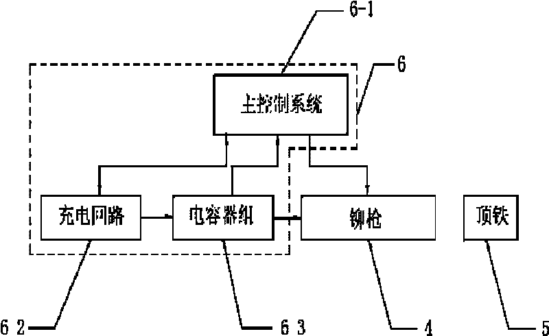
[0031] Specific implementation mode two: combination figure 1 Describe this specific embodiment. The difference between this specific embodiment and the low-voltage electromagnetic riveting method of the metal composite material composite structure described in specific embodiment 1 is that the low-voltage electromagnetic riveting system 6 also includes a main control system 6-1, a charging circuit 6- 2 and the capacitor bank 6-3, the current signal output end of the charging circuit 6-2 is connected to the current signal input end of the capacitor bank 6-3, and the current signal output end of the capacitor bank 6-3 is connected to the coil winding of the riveting gun 4, The control signal input / output end of the main control system 6-1 is connected to the output / input end of the charging circuit 6-2, the current signal output end of the capacitor bank 6-3 is connected to the current signal input end of the main control system 6-1, The control signal output end of the main co...

specific Embodiment approach 3

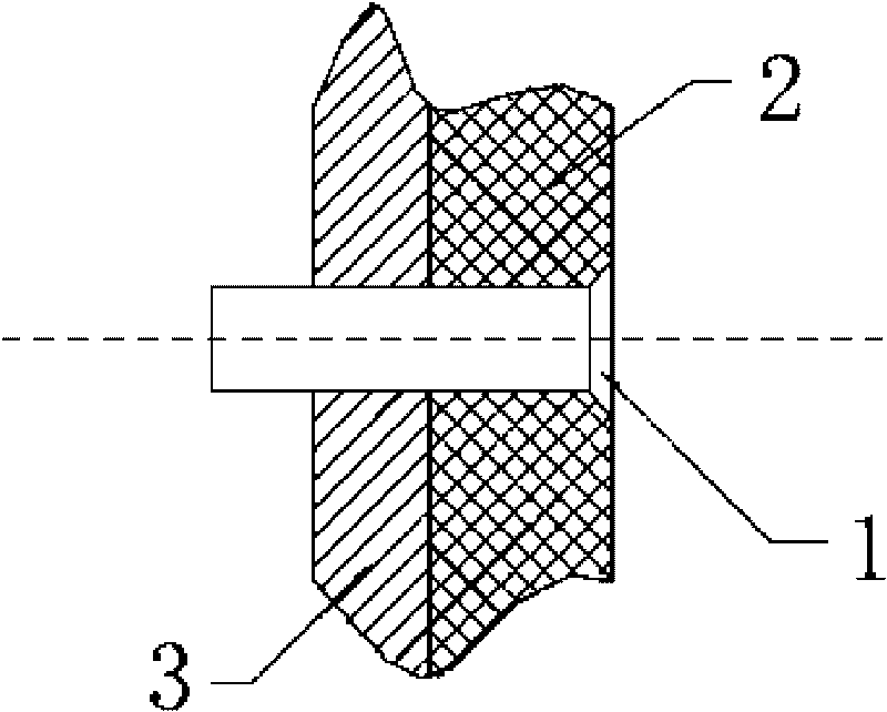
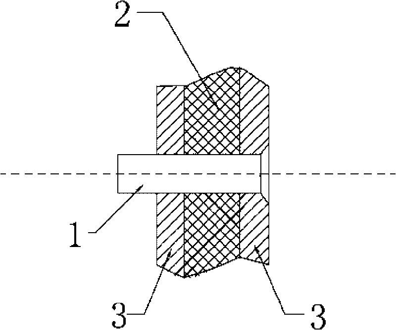
[0033] Specific implementation mode three: combination figure 2 , image 3 with Figure 4 Describe this specific embodiment. The difference between this specific embodiment and the low-voltage electromagnetic riveting method of the metal-composite material composite structure described in specific embodiment 1 or 2 is that the composite structure of the metal 3 and the composite material 2 is two or more layers .


PUM

PropertyMeasurementUnit
diameteraaaaaaaaaa
diameteraaaaaaaaaa
diameteraaaaaaaaaa

Abstract

The invention relates to a low-voltage electromagnet riveting method of a metal-composite material combined structure, belonging to the manufacture filed of aviation and space engineering and solving the problems that the traditional riveting technology is difficult to realize the riveting of rivets with high strength, large diameter and large length on the metal-composite material, the metal-composite material combined structure has unstable riveting quality, the riveted structure has short life and the uniform interference riveting forming of rivets with large length cannot be ensured. The low-voltage electromagnet riveting method of the metal-composite material combined structure comprises the following steps: firstly, fixing metals and composite materials on which through holes are drilled; secondly, leading the rivets to pass through the through holes of the metals and the composite materials; thirdly, contacting a rivet head of a rivet gun with one side of a rivet tail and contacting one side of the rivet tail with top iron; and fourthly, giving out a processing signal to the rivet gun by a low-voltage electromagnetic riveting system and finishing the riveting. The invention is applied in the riveting process of the metal-composite material combined structures of large-sized cylinders of large-sized planes and rocket projectile bodies.

Description

technical field [0001] The invention relates to the field of aviation and aerospace engineering manufacturing, in particular to a method for riveting metal and composite materials on cylindrical structural parts such as large aircraft fuselage, wing and large launch vehicle body. Background technique [0002] Many advanced new technologies and new materials are used in the development and production of my country's new generation of large-scale launch vehicle series and large aircraft projects, which put forward stricter requirements for production technology. Metal-composite materials are a material structure that must be used in rocket bodies, large civil aircraft, and new military aircraft. With the improvement of rocket carrying capacity, the acceleration of cruise speed of missile weapons, and the increase of aircraft take-off weight and flight speed, it is necessary to realize the lightweight of materials and structures. The proportion of composite materials has increa...

Claims


Application Information

Patent Timeline
Patent Type & Authority Applications(China)
IPC IPC(8): B21J15/14B21J15/24
CPCB21J15/24B21J15/147
Inventor 李春峰于海平赵志衡邓将华崔俊佳徐志丹江洪伟
Owner HARBIN INST OF TECH
Why Eureka
Try Eureka