
Crack grouting simulation testing device based on visual detection and testing method

A simulation test and grouting technology, applied in the field of formation fracture grouting, can solve the problems of poor surrounding rock stability, easy formation of formation fractures, poor grouting fluid permeability, etc., and achieves strong practical performance, high simulation accuracy and simple structure. Effect

Inactive Publication Date: 2019-03-29
SHANDONG UNIV OF SCI & TECH
View PDF8 Cites 13 Cited by
  • Summary
  • Abstract
  • Description
  • Claims
  • Application Information

AI Technical Summary

Problems solved by technology

As the burial depth of coal seams continues to increase, the surrounding rocks are subjected to increasing in-situ stress and water pressure, and the fracture characteristics of the strata have also changed, especially the development of micro-pores, and the poor permeability of grouting grout, making it more difficult to determine the grout. The degree of diffusion and the degree of concretion seriously affect the construction period of the well, increasing the difficulty of construction and the cost of the project
[0003] Due to the high ground stress and high water pressure in the deep buried strata, the stability of the surrounding rock is poor during the construction process, and stratum cracks are easily generated. At this stage, grouting construction is difficult. The lack of research data and engineering practice experience in the relationship between the crack rate and the crack rate brings difficulties to the design and construction of underground grouting

Method used


Image

  • Crack grouting simulation testing device based on visual detection and testing method

Examples


Embodiment 1

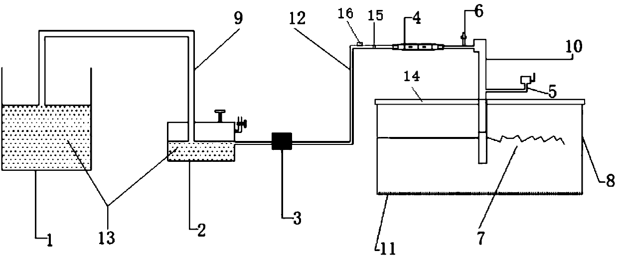
[0045] The invention provides a visual detection crack grouting simulation test device, specifically as figure 1 As shown, it includes a grouting pool 1, a high-pressure grouting pump 2, a monitoring system 3, a one-way valve 4, an overflow valve 5, a pressure limiting valve 6, a simulated crack 7 on the coal seam floor, and a test box 8: in this embodiment, The monitoring system 3 includes flow meters and pressure gauges. The structure and function of each part are as follows:

[0046] The simulated fissure 7 of the coal seam floor is a massive structure, and part of the top surface of the simulated fissure 7 of the coal seam floor is a plane and the other part is an uneven curved surface;

[0047] The grouting tank 1 is used to store the slurry 13, and the grouting tank 1 communicates with the inlet of the high-pressure grouting pump 2 through the first high-pressure pipeline 9;


PUM

PropertyMeasurementUnit
Thicknessaaaaaaaaaa

Abstract

The invention provides a crack grouting simulation testing device based on visual detection and a testing method, and belongs to the field of stratum crack grouting technology. The simulation testingdevice comprises a grouting tank, a high pressure grouting pump, a monitoring system, a check valve, a relief valve, a pressure limiting valve, a coal seam floor simulated crack, and a test box. The grouting tank is connected to an inlet of the high pressure grouting pump through a first high pressure pipeline. The test box is made of a transparent plexiglass plate. A grouting circular hole is formed at the upper end of the test box. The bottom end of the side wall of the test box is provided with a displacement scale. A grouting pipe is provided in the grouting circular hole. The lower end ofthe grouting pipe is inserted into the coal seam floor simulated crack, and the upper end of the grouting pipe is located above the test box. An outlet of the high pressure grouting pump is connectedto the upper end of the grouting pipe through a second high pressure pipe. The monitoring system, the one-way valve and the pressure limiting valve are sequentially arranged on the second high pressure pipeline along the flow direction of a slurry. The relief valve is placed on the grouting pipe. The crack grouting simulation testing device based on the visual detection and the testing method usethe plexiglass test box as an accommodating space, and inject a grout into the coal seam floor simulated crack through the high pressure grouting pump, so as to realize the simulation of a high pressure grouting effect of a coal seam floor crack, which has high practical performance and high simulation precision.

Description

technical field [0001] The invention belongs to the technical field of formation fissure grouting, and in particular relates to a visual detection fissure grouting simulation test device and a test method. Background technique [0002] In the crack grouting construction of the mine strata, the high-pressure grouting technology can fill the cracks in a short time, improve the stability conditions and speed up the construction speed; at the same time, the unstable stratum can be reinforced by grouting to ensure the stability of the surrounding rock. As the depth of the coal seam continues to increase, the ground stress and water pressure on the surrounding rock are also increasing, and the characteristics of the fractures in the formation have also changed, especially the development of micro-pores, and the poor permeability of the grouting slurry, making it more difficult to determine the grout. The degree of diffusion and the degree of concretion have seriously affected the ...

Claims


Application Information

Patent Timeline
IPC IPC(8): G01N33/24G01N13/00G01N13/04
CPCG01N13/00G01N13/04G01N33/24G01N2013/003
Inventor 张文泉朱先祥李伟王在勇白斌高兵
Owner SHANDONG UNIV OF SCI & TECH
Learn More