Electronic device and acoustic wave range finding method thereof

A technology of electronic equipment and sound wave ranging, which is applied in the direction of radio wave measurement system, sound wave re-radiation, measuring device, etc., can solve problems such as inability to measure and affect user experience, and achieve the effect of improving user experience

Active Publication Date: 2019-03-29
HUAWEI TECH CO LTD
11 Cites 0 Cited by

AI-Extracted Technical Summary

Problems solved by technology

[0003] Since the transmission and reception of sound waves requires a certain amount of time (that is, both the transmitted signal and the received signal have a certain rising edge and falling edge), for short-distance tests, if the rising edge and falling edge are relatively gentle, when applied to electronic equipment, It will cause the transmission time and reception time of the acoustic signal to overlap, which cannot be measured, and if the rising edge and falling e...

Abstract

An embodiment of the invention discloses an electronic device and an acoustic wave range finding method thereof. According to the method, first sound wave signals of first and second frequency signals, namely double acoustic multi-frequency signals, are emitted, and distance between the electronic device and a target barrier is calculated according to a time difference between the first and secondfrequency signals in a first reception signal corresponding to the first acoustic wave signal. The problem that a measurement result cannot be obtained due to overlapping of emission time and reception time of the acoustic wave signal can be overcome; The acoustic wave signal is avoided from generating POP sound (an interference signal of an audio sub system) that can be heard by people because that the first and second frequency signals do not include harmonic waves in the audio field after mutual modulation; and the user experience is improved.

Application Domain

Acoustic wave reradiation

Technology Topic

Time differenceAudio frequency +7

Image

  • Electronic device and acoustic wave range finding method thereof
  • Electronic device and acoustic wave range finding method thereof
  • Electronic device and acoustic wave range finding method thereof

Examples

  • Experimental program(1)

Example Embodiment

[0069] The technical solutions in the embodiments of the present application will be described clearly and completely in conjunction with the accompanying drawings in the embodiments of the present application. Obviously, the described embodiments are only a part of the embodiments of the present application, rather than all the embodiments. Based on the embodiments in this application, all other embodiments obtained by those of ordinary skill in the art without creative work fall within the protection scope of this application.
[0070] In the following description, many specific details are explained in order to fully understand this application, but this application can also be implemented in other ways different from those described here, and those skilled in the art can do so without departing from the connotation of this application. Similar promotion, therefore, this application is not limited by the specific embodiments disclosed below.
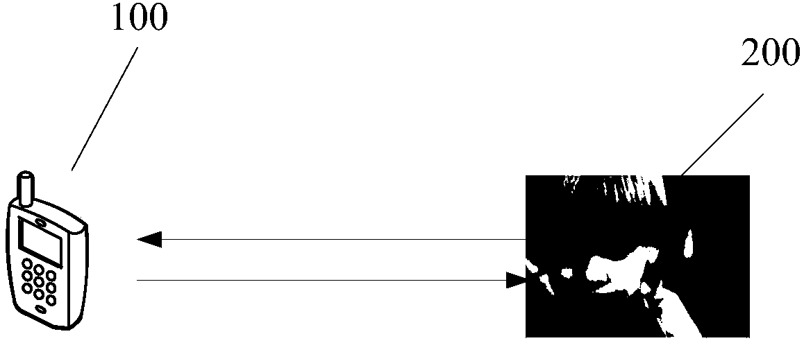
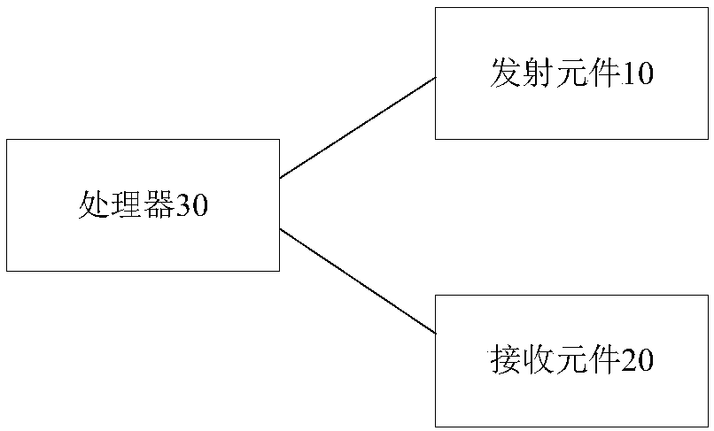
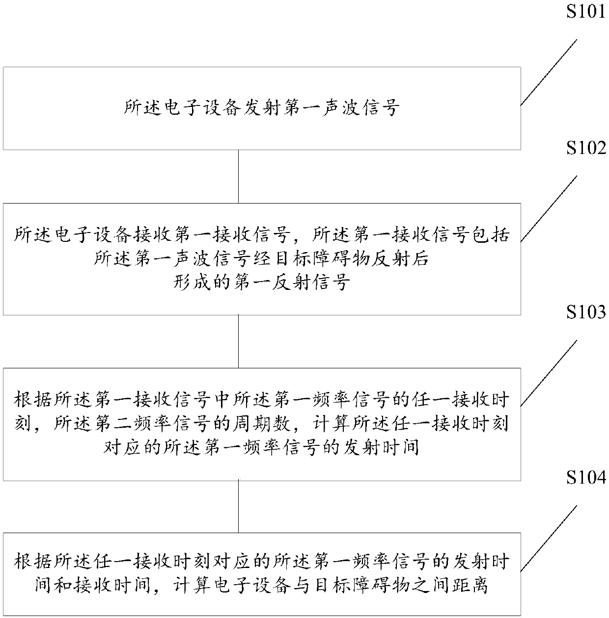
[0071] The embodiments of the present application provide an electronic device and a sound wave ranging method thereof. Such as figure 1 As shown, figure 1 This is a schematic diagram of a scenario of an electronic device application provided by an embodiment of this application. Wherein, the electronic device 100 transmits a sound wave signal to the target obstacle 200, and receives a reflection signal formed by the sound wave signal reflected by the target obstacle 200, and then based on the transmission time of the sound wave signal and the reflection signal The distance between the electronic device 100 and the target obstacle 200 is determined.
[0072] For specific applications, such as figure 2 As shown, the electronic device 100 includes a transmitting element 10, a receiving element 20, and a processor 30, where the transmitting element 10 can be a speaker, an earpiece, a piezoelectric ceramic element, or other elements that can convert electrical signals into acoustic signals. As a component of the electronic device screen or frame of the sound cavity of the piezoelectric ceramic element, the receiving element 20 can be a microphone or piezoelectric ceramic element that can convert sound wave signals into electrical signals, which is not limited in this application. , Depending on the situation. The processor 30 is configured to output electrical signals to the transmitting element 10 and receive the electrical signals output by the receiving element 20, and then according to the electrical signals output to the transmitting element 10 and the received receiving element 20 The output electrical signal is used to calculate the distance between the electronic device 100 and the target obstacle 200. For the specific processing process, please refer to the description in the following embodiments.
[0073] It should be noted that the electronic device provided in the embodiments of the present application can be applied to the distance measurement of the camera of a mobile phone. When the processor outputs the distance between the electronic device and the target obstacle to the camera, the camera can take pictures. It can also replace the low beam sensor to detect target obstacles near the earpiece. When detecting a target obstacle near the earpiece position, the electronic device is considered to be close to the head, and the display screen of the electronic device is turned off And the touch screen can also be used for other short-distance measurements, which is not limited in this application, and it depends on the situation.
[0074] The electronic device and its acoustic ranging method provided by the embodiments of the present application will be described in detail below.
[0075] Such as image 3 As shown, the embodiment of the present application provides a sound wave ranging method applied to an electronic device, and the method includes:
[0076] S101: The electronic device emits a first acoustic wave signal to a target obstacle, the first acoustic wave signal includes a first frequency signal and a second frequency signal, and the first frequency signal and the second frequency signal are mutually modulated After that, there is no audible frequency signal to the human ear, that is, after the first frequency signal and the second frequency signal are mutually modulated, there is no harmonic in the audio field, so that the electronic device can easily distinguish the original The sound wave signal in the application and the interference signal in nature, so as to prevent the sound wave signal from generating POP sounds that are audible to human ears (the POP sound is the pop sound of the audio subsystem, which is a kind of interference signal), and improves user experience . In the embodiment of the present application, the first frequency signal and the second frequency signal are respectively periodic signals, and the least common multiple of the period of the first frequency signal and the period of the second frequency signal is greater than the first frequency signal. The preset value, for example, the first preset value is not less than 1000 microseconds or the least common multiple period includes 20 periods of the first frequency signal, so as to reduce the first sound wave signal emitted by the electronic device and its detection The first reflected signal is obtained, and the probability that the first sound wave signal needs to go back and forth between the electronic device and the target obstacle is calculated. Wherein, the greater the first preset value is, the electronic device uses the first sound wave signal it emits and the detected first reflection signal to calculate that the sound wave signal is between the electronic device and the target obstacle The smaller the probability of error in the time required for a round trip.
[0077] Specifically, in an embodiment of the present application, the audible frequency signal of the human ear is a frequency signal of 20Hz-20000Hz, and after the first frequency signal and the second frequency signal are mutually modulated, there is no human ear The audible frequency signal includes that after the first frequency signal and the second frequency signal are mutually modulated, there is no frequency signal in the range of 20 Hz-20000 Hz, but this application is not limited to this, and it depends on the situation.
[0078] On the basis of the above-mentioned embodiment, in one embodiment of the present application, when the electronic device transmits the first acoustic wave signal to the target obstacle, it also records the emission time of the first acoustic wave signal. This is not limited, as long as it is ensured that the electronic device can obtain the emission time of the first acoustic wave signal, so as to facilitate subsequent time calculations.
[0079] On the basis of the foregoing embodiment, in an embodiment of the present application, the first frequency signal and the second frequency signal are both ultrasonic signals, which is not limited in the present application, and it depends on the situation. In the following, taking the first frequency signal and the second frequency signal as an ultrasonic signal as an example, the electronic device and the acoustic ranging method provided by the embodiment of the present application will be described.
[0080] In a specific application scenario of this application, the first frequency signal is an ultrasonic signal with a frequency of 20KHz, and the second frequency signal is an ultrasonic signal with a frequency of 31KHz, but this application is not limited in this regard. In other embodiments of the application, the first frequency signal and the second frequency signal may also be sound wave signals of other frequencies, as long as the frequency difference between the first frequency signal and the second frequency signal is greater than The second preset value enables the processor to clearly distinguish the first frequency signal and the second frequency signal from the first received signal when receiving the reflected signal. It should be noted that the second preset value may be 2K, or 3K or other values, which is not limited in this application, and it depends on the processing capability of the processor.
[0081] S102: The electronic device receives a first received signal, where the first received signal includes a first reflected signal formed after the first acoustic wave signal is reflected by the target obstacle.
[0082] In the embodiment of the present application, after the receiving element receives the first received signal, it converts it into an analog electrical signal and outputs it to a processor, and the processor converts the analog electrical signal into a digital electrical signal After that, follow-up processing is performed.
[0083] It should be noted that since the main processor of the electronic device does not have the ability to convert analog signals into digital signals, while the audio processor has the ability to convert analog signals into digital signals, therefore, in the embodiments of the present application, the The processor 30 may be an audio processor of the electronic device, or may be as Figure 4 The audio processor 31 and the main processor (ie, CPU) 32 are both shown. This application does not limit this, and it depends on the situation.
[0084] On the basis of any of the foregoing embodiments, in an embodiment of the present application, when the electronic device receives the first received signal, it also records the receiving time of the first received signal. It is not limited, as long as the receiving time of the first received signal can be obtained to facilitate subsequent time calculations.
[0085] It should be noted that since the first frequency signal is a periodic signal, the second frequency signal is also a periodic signal, and the first acoustic wave signal includes multiple periods of first frequency signals and multiple Periodic second frequency signal. Therefore, when the electronic device records the first received signal, it may only record the start time of the first received signal, or record the first received signal in the first received signal. The receiving time of each cycle of a frequency signal and/or the receiving time of each cycle of the second frequency signal is not limited in this application, and it depends on the situation.
[0086] S103: Calculate the transmission time of the first frequency signal corresponding to any receiving moment of the first frequency signal according to the number of cycles of the second frequency signal at any receiving moment of the first frequency signal in the first received signal .
[0087] Taking the first frequency signal as a 20KHz frequency signal and the second frequency signal as a 31KHz frequency signal as an example, the period of the first frequency signal is 50 microseconds, and the period of the second frequency signal is 32.25806452 subtle. As shown in Table 1, the time when the electronic device transmits one cycle of the first frequency signal corresponds to 1.55 cycles of the second frequency signal, and the time when the electronic device transmits two cycles of the first frequency signal corresponds to 3.1 cycles The second frequency signal.......
[0088] Table 1
[0089]
[0090] It can be seen from Table 1 that in different periods of the first frequency signal, the number of periods of the second frequency signal is different. Therefore, in an embodiment of the present application, according to the first received signal At any receiving moment of a frequency signal, the number of cycles of the second frequency signal, and calculating the transmission time of the first frequency signal corresponding to the any receiving moment includes: according to the first received signal in the first received signal In any period of a frequency signal, the number of periods of the second frequency signal is used to calculate the transmission time of the first frequency signal corresponding to the any period. Specifically, after the first received signal is received, any period of the second frequency signal in any period of the first frequency signal in the first received signal can be obtained. The number of periods in each period of the first frequency signal is used to calculate the transmission time of the first frequency signal corresponding to any period.
[0091] It can be seen from Table 1 that in different periods of the first frequency signal, the difference in the number of periods of the first frequency signal and the second frequency signal is different. Therefore, in other embodiments of the present application, when receiving After the first received signal, it may also be based on the difference in the number of cycles of the first frequency signal and the second frequency signal in any period of the first frequency signal in the first received signal, The number of periods of the any period in each period of the first frequency signal is obtained, so as to calculate the transmission time of the first frequency signal corresponding to the any period. This application does not limit this, and it depends on the situation.
[0092] It should be noted that, on the basis of the above-mentioned embodiment, in an embodiment of the present application, the processor can be based on the first received signal in any period of the first frequency signal, the first The difference in the number of cycles between the frequency signal and the second frequency signal (or according to the period value of the second frequency signal in any cycle of the first frequency signal in the first received signal), directly calculate the any A period is the number of periods in each period of the first frequency signal to calculate the transmission time of the first frequency signal corresponding to any period. In another embodiment of the present application, the processor may also be based on the period of the first frequency signal and the second frequency signal in any period of the first frequency signal in the first received signal. Number difference value (or according to the period value of the second frequency signal in any period of the first frequency signal in the first received signal), by querying a preset database to obtain that any period is in the first The number of cycles in each cycle of the frequency signal, so as to calculate the transmission time of the first frequency signal corresponding to any one of the cycles, wherein the preset database stores the content in Table 1, which is incorporated in this application No restrictions, depending on the situation.
[0093] On the basis of the foregoing embodiment, in an embodiment of the present application, when the method for establishing the preset database includes:
[0094] Calculating the number of periods of the second frequency signal corresponding to each period of the multiple periods of the first frequency signal;
[0095] Use the number of periods of the second frequency signal corresponding to each period of the first frequency signal to subtract the number of periods of the first frequency signal in the period to obtain multiple periods of the first frequency signal The difference between the number of cycles of the first frequency signal and the second frequency signal within each cycle time;
[0096] Establish each period of the first frequency signal, the number of periods of the second frequency signal in each period of the first frequency signal, and the first frequency signal and the second frequency in each period of the first frequency signal The corresponding relationship of the difference in the number of periods of the signal is stored and stored to form the preset database.
[0097] S104: Calculate the distance between the electronic device and the target obstacle according to the transmission time and the reception time of the first frequency signal corresponding to any receiving moment.
[0098] After obtaining the transmitting time and receiving time of the first frequency signal corresponding to any receiving moment, the speed of sound and the time difference between the transmitting time and receiving time of the first frequency signal corresponding to any receiving moment can be used to calculate Get the distance between the electronic device and the target obstacle.
[0099] On the basis of the foregoing embodiment, in an embodiment of the present application, the electronic device and the target obstacle are calculated according to the transmission time and reception time of the first frequency signal corresponding to any one of the receiving moments. The distance includes: calculating the distance between the electronic device and the target obstacle according to the transmitting time and receiving time of the first frequency signal corresponding to any period, but this application does not Make restrictions, depending on the situation.
[0100] In the embodiment of the present application, even if the received first received signal includes a conductive signal from the body of the electronic device, the number of cycles of the second frequency signal in each cycle of the first frequency signal (the In each cycle of the first frequency signal, the difference between the number of cycles of the first frequency signal and the second frequency signal), calculate the difference between the transmission time and the reception time of the first frequency signal corresponding to any cycle The time difference is used to calculate the distance between the electronic device and the target obstacle.
[0101] It can be seen that the acoustic wave ranging method provided by the embodiment of the present application can transmit a dual-tone multi-frequency signal, that is, a first acoustic wave signal including a first frequency signal and a second frequency signal, according to the first acoustic wave The period difference between the first frequency signal and the second frequency signal in the first received signal corresponding to the signal is calculated to obtain the distance between the electronic device and the target obstacle, avoiding the overlap between the transmission time and the reception time of the acoustic signal The problem of not being able to obtain measurement results. At the same time, since the first frequency signal and the second frequency signal are mutually modulated, there is no audible frequency signal to the human ear, which prevents the sound wave signal from generating POP sound audible to the human ear. (The POP sound is the pop sound of the audio subsystem, which is a kind of interference signal), which improves the user experience.
[0102] The embodiment of the present application provides another electronic device and its acoustic ranging method. The description is continued by taking the ultrasonic signal with the first frequency signal of 20K and the ultrasonic signal with the second frequency signal of 31K as examples. In the embodiment of the present application, the acoustic wave ranging method includes:
[0103] S201: The electronic device transmits a first acoustic wave signal to a target obstacle, where the first acoustic wave signal includes a first frequency signal and a second frequency signal, and the first frequency signal and the second frequency signal are mutually modulated After that, there is no frequency signal audible to the human ear. The first frequency signal is a periodic signal, the second frequency signal is a periodic signal, and the period of the first frequency signal is equal to the period of the second frequency signal. The least common multiple of the period is greater than the first preset value.
[0104] S202: The electronic device receives a first received signal, where the first received signal includes a first reflected signal formed after the first acoustic wave signal is reflected by the target obstacle.
[0105] S203: According to the number of cycles of the second frequency signal (F2) at any receiving time of the first frequency signal (F1) in the first received signal, calculate the first frequency signal corresponding to the any receiving time. The transmission time of a frequency signal.
[0106] As shown in Table 2, Table 2 shows the wavelength of the first frequency signal F1, the wavelength of the second frequency signal F2, the total length of wavelengths corresponding to different periods of the first frequency signal, the transmission end time corresponding to different periods of the first frequency signal, and the first frequency signal. The number of periods (or wavelengths) of the second frequency signal corresponding to different periods of a frequency signal, the wavelength remainder of the second frequency signal corresponding to different periods of the first frequency signal, and the remainder wavelength of the second frequency signal corresponding to different periods of the first frequency signal The number of sampling points included in the remainder wavelength of the second frequency signal corresponding to different periods of the first frequency signal, and the number of sampling points included in the remainder wavelength of the second frequency signal corresponding to different periods of the first frequency signal are rounded up. It should be noted that in this embodiment, the preset sampling frequency is 6.144 MHz, but this application is not limited to this. In other embodiments of this application, it can also be other values, depending on the situation. set.
[0107] Table 2:
[0108]
[0109]
[0110]
[0111]
[0112] It can be seen from Table 2 that different periods of the first frequency signal correspond to different total wavelengths, different periods of the first frequency signal correspond to different emission end times, and different periods of the first frequency signal correspond to the number of periods (or wavelengths) of the second frequency signal. The wavelength remainders of the second frequency signals corresponding to different periods of the first frequency signal are not completely the same, the remainder wavelengths of the second frequency signals corresponding to different periods of the first frequency signal are not completely the same, and the second frequency signals corresponding to different periods of the first frequency signal are not completely the same. The number of sampling points included in the remainder wavelength of the frequency signal is not completely the same, and the rounding results of the number of sampling points included in the remainder wavelength of the second frequency signal corresponding to different periods of the first frequency signal are not completely the same.
[0113] And when the number of cycles of the first frequency signal is not greater than 20 (that is, when the transmission time of the first acoustic wave signal is not greater than 1000 microseconds), among the remaining wavelengths of the second frequency signal corresponding to different cycles of the first frequency signal The number of sampling points included is completely different, and the rounding results of the number of sampling points included in the remainder wavelength of the second frequency signal corresponding to different periods of the first frequency signal are completely different. Therefore, in the embodiment of the present application, when the first received signal is received According to the number of sampling points included in the remainder wavelength of the second frequency signal in any period of the first frequency signal or the rounding result thereof, the specific emission time corresponding to the any period can be obtained.
[0114] Therefore, on the basis of the above-mentioned embodiment, in one embodiment of the present application, according to any receiving moment of the first frequency signal in the first received signal, the number of cycles of the second frequency signal is calculated The transmitting time of the first frequency signal corresponding to any receiving moment includes:
[0115] According to the number of cycles of the second frequency signal in any cycle of the first frequency signal in the first received signal, calculate within any cycle of the first frequency signal in the first received signal, The difference between the number of cycles of the first frequency signal and the second frequency signal;
[0116] According to the difference in the number of cycles between the first frequency signal and the second frequency signal in any cycle of the first frequency signal in the first received signal, the first frequency signal within the cycle number difference time is calculated Number of wavelengths of two frequency signals;
[0117] Calculating the number of sampling points corresponding to the number of wavelengths of the second frequency signal within the period difference time under the preset sampling frequency;
[0118] Query a preset database according to the number of sampling points to obtain the transmission time of the first frequency signal corresponding to any period;
[0119] Wherein, the preset database stores the correspondence relationship between the transmission time of the first frequency signal and the preset number of sampling points within different transmission periods of the first frequency signal, and the preset number of sampling points is the preset At the sampling frequency, the number of sampling points of the second frequency signal within the period of difference between the number of cycles of the first frequency signal and the second frequency signal in the transmission period.
[0120] On the basis of the foregoing embodiment, in another embodiment of the present application, the number of wavelengths of the second frequency signal within the period number difference time is composed of M wavelengths and N wavelengths, where M is not less than An integer of zero, N is greater than zero and less than 1. Under the calculation of the preset sampling frequency, the number of sampling points corresponding to the number of wavelengths of the second frequency signal within the period difference time includes:
[0121] Calculate the number of sampling points corresponding to N wavelengths among the number of wavelengths of the second frequency signal within the period difference time under the preset sampling frequency; then query the preset database according to the number of sampling points corresponding to the N wavelengths to obtain all The transmission time of the first frequency signal corresponding to any one of the periods.
[0122] It should be noted that in the foregoing embodiment, in order to reduce the amount of data calculation of the processor and improve processing efficiency, in any period of obtaining the first frequency signal, the remainder wavelength of the second frequency signal includes After the number of sampling points or the rounding result thereof, the number of sampling points included in the remainder wavelength of the second frequency signal or the rounding result in any period of the first frequency signal is obtained by querying the preset database. The specific transmission time corresponding to the period. However, this application is not limited to this. In other embodiments of the present application, it can also be based on the number of sampling points included in the remainder wavelength of the second frequency signal in any period of the first frequency signal or its rounding result , The specific transmission time corresponding to any period is directly calculated, which is not limited in this application, and it depends on the situation.
[0123] It should also be noted that in the above-mentioned embodiment, the preset database may store all the contents in Table 2 or part of the contents in Table 2, as long as it includes any period of the first frequency signal. Within, the number of sampling points included in the remainder wavelength of the second frequency signal (or its rounded result) and the corresponding emission time of any period are sufficient.
[0124] Specifically, in an embodiment of the present application, the method for establishing the preset database includes:
[0125] Calculating the number of periods of the second frequency signal corresponding to each period of the multiple periods of the first frequency signal;
[0126] Divide the number of cycles of the second frequency signal into P cycles and Q cycles, where P is an integer not less than zero, and Q is greater than zero and less than 1;
[0127] Calculating the wavelength length of the second frequency signal corresponding to the Q cycles;
[0128] Calculating the number of sampling points included in the wavelength length of the second frequency signal corresponding to the Q cycles under the preset frequency;
[0129] A correspondence relationship between the number of sampling points and each cycle time of the first frequency signal is established.
[0130] On the basis of the foregoing embodiment, in an embodiment of the present application, in order to improve the query efficiency of the preset database, the method for establishing the preset database is to calculate the preset frequency, and the Q cycles correspond to The number of sampling points included in the wavelength length of the second frequency signal further includes: rounding the number of sampling points included in the wavelength length of the second frequency signal corresponding to the Q cycles at a preset frequency; establishing the The corresponding relationship between the result of rounding the number of sampling points and each cycle time of the first frequency signal. This application does not limit this, and it depends on the situation.
[0131] S204: Calculate the distance between the electronic device and the target obstacle according to the transmitting time and the receiving time of the first frequency signal corresponding to any receiving moment.
[0132] Since S201, S202, and S204 are the same as S101, S102, and S104 in the foregoing embodiment, they will not be described in detail in this embodiment.
[0133] The embodiment of the present application provides yet another electronic device and its acoustic ranging method. The description is continued by taking the first frequency signal being an ultrasonic signal of 20KHz and the second frequency signal being an ultrasonic signal of 31KHz as an example. It can be seen from Table 2 that when the rounded result of the number of sampling points included in the remainder wavelength of the second frequency signal in any period of the first frequency signal is used as the query factor, in the first frequency signal of 20 cycles, The rounding result of each period of the first frequency signal and the number of sampling points included in the remainder wavelength of the corresponding second frequency signal is in a one-to-one relationship, and any period of the first frequency signal in the preset database Within, the cycle period of the rounding result of the number of sampling points included in the remainder wavelength of the second frequency signal is 1000 microseconds. In order to ensure that the first reflected signal formed by the reflection of the first acoustic wave signal by the target obstacle can be received, in an embodiment of the present application, the transmission time of the first acoustic wave signal is 2 ms, that is, The first acoustic wave signal includes a signal with two cycles, and the electronic device emitting the first acoustic signal includes: the electronic device emits the first acoustic signal with two cycles, and in the subsequent processing, the first The signal at the falling edge of the two cycles is used as the processing signal.
[0134] Specifically, in the embodiments of this application, such as Figure 5 As shown, the sound wave ranging method includes:
[0135] S301: The electronic device transmits a first acoustic wave signal to a target obstacle, the first acoustic wave signal includes a first frequency signal and a second frequency signal, and the first frequency signal and the second frequency signal are mutually modulated There is no audible frequency signal for human ears. The first frequency signal is a periodic signal, the second frequency signal is a periodic signal, and the period of the first frequency signal is equal to the period of the second frequency signal. The least common multiple of the period is greater than the first preset value;
[0136] S302: The electronic device receives a first received signal, where the first received signal includes a first reflected signal formed by the first acoustic signal reflected by the target obstacle; it should be noted that in this embodiment , The first received signal not only includes the first reflected signal formed by the first acoustic wave signal reflected by the target obstacle, but also includes the first reflected signal transmitted from the first acoustic wave signal through the electronic device body Acoustic signal and environmental noise signal, etc.
[0137] S303: Perform filtering processing on the first received signal to remove interference signals such as environmental noise signals in the first received signal, and only retain the first acoustic signal to be conducted to the receiving element through the electronic device body And the first reflected signal formed after the first acoustic signal is reflected by the target obstacle.
[0138] S304: Acquire the envelope data of the first received signal, and select the signal of the falling edge part of the second cycle of the first received signal from the envelope data of the first received signal as the first subsequent processing. receive signal. It should be noted that when selecting the signal at the falling edge of the second cycle from the envelope data of the first received signal, it may be determined whether the signal strength in the envelope data of the first received signal is gradually increased or gradually increased. Attenuate, determine the falling edge area of ​​the second cycle.
[0139] S305: Perform frequency domain filtering on the first received signal, and obtain independent first frequency signals and second frequency signals from the first received signal.
[0140] S305: Square wave the first frequency signal and the second frequency signal to obtain a first square wave signal corresponding to the first frequency signal and a second square wave corresponding to the second frequency signal Signal to facilitate subsequent data operations.
[0141] S306: Perform shaping and correction on the first square wave signal and the second square wave signal, and remove signals with poor quality in the first square wave signal and the second square wave signal. When there is no better quality signal in the square wave signal and the second square wave signal, return to S301, and when there is a better quality signal in the first square wave signal and the second square wave signal, execute S307.
[0142] It should be noted that, in the embodiment of the present application, the first square wave signal and the second square wave signal are shaped and corrected, and the quality in the first square wave signal and the second square wave signal is removed. There are many methods for bad signals. For example, when the frequencies of the first frequency signal and the second frequency signal are 20KHz and 31KHz, the number of corresponding sampling points in each cycle is determined, and square wave is performed. Later, the number of 1 and -1 can also be determined. For example, in a cycle of 20KHz, at 6.144M sampling rate, the number of sampling points is 307.2, then the number of 1 and -1 points should be about 153 to 154. If it is found that the number of points of 1 is 152, and the number of points of -1 is 155, Then it can be adjusted to 153 and 154, which is equivalent to improving the quality of the signal. If the number of 1 becomes 120 and the number of -1 becomes 187, then this data can be judged as a poor quality signal and throw it away.
[0143] S307: Select any receiving time from the area with better signal quality in the first square wave signal and the second square wave signal, and obtain the residual wavelength of the second square wave signal at any receiving time The sampling points included in the rounding result. Specifically, in an embodiment of the present application, from the region with better signal quality in the first square wave signal and the second square wave signal, any period is selected, and the any period is obtained. The result of rounding the sampling points included in the remainder wavelength of the second square wave signal.
[0144] S308: According to the rounding result of the sampling points included in the remainder wavelength of the second square wave signal at any receiving moment, query a preset database to obtain the transmission time of the first frequency signal corresponding to any receiving moment And receiving time. Specifically, in an embodiment of the present application, according to the result of rounding sampling points included in the remainder wavelength of the second square wave signal in any period, query a preset database to obtain any period The transmitting time and receiving time of the corresponding first frequency signal.
[0145] S309: Calculate the distance between the electronic device and the target obstacle according to the transmission time and the reception time of the first frequency signal corresponding to any one of the receiving moments. Specifically, in an embodiment of the present application, according to the transmission time and reception time of the first frequency signal corresponding to any period, the flight time measurement method is used to calculate the distance between the electronic device and the target obstacle. distance.
[0146] S310: Determine whether the measured distance calculated in S309 obviously violates common sense, and if it violates common sense, delete the data and return to S307 or S301.
[0147] It should be noted that the electronic device and its acoustic wave ranging method provided in the embodiments of the present application can not only be applied to short-distance measurement, but also can be applied to longer-distance measurement. When the transmitting element emits the first acoustic wave When there is no overlap between the time when the signal is transmitted to the receiving element through the body of the electronic device and the time when the first reflected signal formed by the reflection of the first acoustic wave signal by the target obstacle propagates to the receiving element, the acoustic wave The ranging method S304 further includes: determining the area where the first reflected signal is located from the envelope data of the first received signal, and then selecting the area of ​​the first reflected signal from the area where the first reflected signal is located. The falling edge portion is used as the first received signal for subsequent processing to reduce the amount of calculation for subsequent data processing. Such as Image 6 As shown, since the first acoustic wave signal is transmitted to the receiving element through the electronic device body, the signal C is significantly stronger than the first reflected signal formed after the first acoustic wave signal is reflected by the target obstacle. The strength of the signal D to the receiving element. Therefore, in the embodiment of the present application, when the envelope data of the first received signal is obtained, the envelope data of the first received signal can be easily distinguished. The part of the first received signal that is transmitted from the first acoustic wave signal to the receiving element through the body of the electronic device and the first reflected signal formed after the first acoustic wave signal is reflected by the target obstacle propagates to The part of the receiving element.
[0148] It should be noted that since the transmission time of the first acoustic wave signal is 2ms and the waiting time for return is 12ms, plus the subsequent data processing time, it may take as long as 30ms to obtain a measurement result. When increasing the measurement speed of the acoustic distance measurement method for multiple times, on the basis of any of the above embodiments, in an embodiment of the present application, the electronic device may use the emitting element to sequentially emit multiple Acoustic signal of frequency combination. Specifically, on the basis of any of the foregoing embodiments, in an embodiment of the present application, the acoustic distance measurement method further includes:
[0149] The electronic device transmits a K-th sound wave signal to the target obstacle. The K-th sound wave signal includes an X-th frequency signal and a Y-th frequency signal. The X-th frequency signal and the Y-th frequency signal are not mutually modulated. There is a frequency signal audible to the human ear, the Xth frequency signal is a periodic signal, the Yth frequency signal is a periodic signal, and the period of the Xth frequency signal is equal to the period of the Yth frequency signal. The least common multiple is greater than the first preset value;
[0150] The electronic device receives the Kth received signal, where the Kth received signal includes a Kth reflected signal formed by the Kth acoustic signal reflected by the target obstacle;
[0151] Calculating the transmission time of the X-th frequency signal corresponding to any one of the receiving moments according to the number of cycles of the Y-th frequency signal at any receiving time of the X-th frequency signal in the K-th received signal;
[0152] Calculate the distance between the electronic device and the target obstacle according to the transmission time and the reception time of the Xth frequency signal corresponding to any one of the receiving moments;
[0153] Among them, the value of K starts from 2 and loops to G, K is a natural number and increases by 1 during each iteration, G is a positive integer greater than 1, and the frequency signals included in any two acoustic signals are completely different.
[0154] It should be noted that on the basis of the foregoing embodiment, in an embodiment of the present application, the first acoustic wave signal and the Jth acoustic wave signal are any two acoustic wave signals from the first acoustic wave signal to the Gth acoustic wave signal, and The transmission time of the Jth acoustic wave signal is later than the transmission time of the first acoustic wave signal;
[0155] When the frequency difference between the first I sound wave signal and the Jth sound wave signal is less than or equal to a second preset value, the transmission time of the J sound wave signal and the reception time of the first received signal are different. overlap;
[0156] When the frequency difference between the first I acoustic wave signal and the Jth acoustic wave signal is greater than a second preset value, the emission time of the J acoustic wave signal and the emission time of the first acoustic wave signal do not overlap , Where I and J are natural numbers, and 1≤I≤G, 1≤J≤G.
[0157] Table 3 shows the transmission time layout of multiple acoustic wave signals in the acoustic wave ranging method provided by an embodiment of the present application. As shown in Table 3, taking G as an example, the first acoustic signal includes an ultrasonic signal with a frequency of 20KHz and an ultrasonic signal with a frequency of 31KHz, and the second acoustic signal includes an ultrasonic signal with a frequency of 21KHz and the frequency Is a 32KHz ultrasonic signal, the third sonic signal includes an ultrasonic signal with a frequency of 23KHz and an ultrasonic signal with a frequency of 34KHz, and the fourth sonic signal includes an ultrasonic signal with a frequency of 24KHz and an ultrasonic signal with a frequency of 35KHz. The fifth sonic signal includes an ultrasonic signal with a frequency of 25KHz and an ultrasonic signal with a frequency of 36KHz, and the sixth sonic signal includes an ultrasonic signal with a frequency of 26KHz and an ultrasonic signal with a frequency of 38KHz.
[0158] table 3
[0159]
[0160]
[0161] It can be seen from Table 3 that the frequency difference between the fifth ultrasonic signal and the first ultrasonic signal is relatively large, which will not cause the processor to be difficult to distinguish. Therefore, the transmission time of the fifth ultrasonic signal should not be earlier than The transmission end time of the first ultrasonic signal is sufficient, and the frequency difference between the second ultrasonic signal and the first ultrasonic signal is small, which may cause the processor to be difficult to distinguish. Therefore, the transmission of the second ultrasonic signal The time is later than the receiving time of the first ultrasonic signal.
[0162] It should be noted that, in the above-mentioned embodiments, the transmission time and reception time of each ultrasonic signal and the frequency signal included in each ultrasonic signal are all examples for facilitating the understanding of the solution of the present application, and do not describe the technology of the present application. The plan causes limitations, which can be determined according to actual application requirements.
[0163] In summary, the acoustic wave ranging method provided by the embodiments of the present application can transmit a dual-tone multi-frequency signal, that is, transmit a first acoustic wave signal including a first frequency signal and a second frequency signal, according to the first acoustic wave The period difference between the first frequency signal and the second frequency signal in the first received signal corresponding to the wave signal is calculated to obtain the distance between the electronic device and the target obstacle, which avoids the interaction between the transmission time and the reception time of the sound wave signal. The problem that the measurement results cannot be obtained due to overlapping, and since the first frequency signal and the second frequency signal are mutually modulated, there is no audible frequency signal to the human ear, which prevents the sound wave signal from generating POP that is audible to the human ear. Sound (the POP sound is the pop sound of the audio subsystem, which is a kind of interference signal), which improves the user experience.
[0164] The embodiment of the present application also provides another electronic device and its acoustic wave ranging method. The acoustic wave ranging method includes:
[0165] S401: The electronic device transmits a first acoustic wave signal, where the first acoustic wave signal is a linear frequency modulated (LFM) signal, and there is no frequency signal audible to human ears in the first acoustic wave signal. For example, the frequency range of the first acoustic wave signal may be 20KHz-40KHz, which is not limited in this application, and it depends on the situation.
[0166] It should be noted that the LFM signal (Linear Frequency Modulation, also known as chirp signal) is a common modulation signal in the field of radar ranging. Use a matched filter to compress the received signal to maximize the signal-to-noise ratio of the output signal to determine the pulse echo time and achieve the purpose of ranging.
[0167] Specifically, the mathematical expression of the LFM signal is: Where f c Is the carrier frequency; Is a rectangular signal, and its expression is Is the frequency modulation slope, B is the signal bandwidth, T is the pulse period; j is the imaginary symbol.
[0168] From the above formula, the instantaneous frequency of the LFM signal is In order to prevent the first sound wave signal from generating a signal audible to the human ear, the first sound wave signal in the embodiment of the present application is the result of multiplying the mathematical expression of the LFM signal and the fade-in and fade-out function. Specifically, in an embodiment of the present application, the expression of the fade function is: However, this application does not limit this, as long as it is ensured that the first sound wave signal obtained after the mathematical expression of the LFM signal is multiplied by the function does not have a frequency signal audible to the human ear.
[0169] Such as Figure 7 with Figure 8 As shown, Figure 7 with Figure 8 Two kinds of the LFM signal frequency domain waveform diagram and time domain waveform diagram are shown.
[0170] S402: The electronic device receives a first received signal, where the first received signal includes a first reflected signal formed after the first acoustic wave signal is reflected by the target obstacle.
[0171] S403: Compare the first received signal with a preset free-field reference signal to obtain a first reflected signal in the first received signal.
[0172] On the basis of the above-mentioned embodiment, in an embodiment of the present application, the method for obtaining the free-field reference signal includes: transmitting a first signal in an obstacle-free environment (theoretical obstacle is located in an infinite distance environment). Acoustic signal. At this time, the signal received by the receiving element is used as a free-field reference signal.
[0173] It should be noted that the free-field reference signal includes diffraction signals, body conduction signals, various noise signals, etc., except for all signals other than the first reflected signal formed by the first acoustic signal reflected by the target obstacle. , And the first received signal includes various signals in the free-field reference signal and the first reflected signal formed after the first acoustic wave signal is reflected by the target obstacle. Therefore, the first received signal Comparing with the preset free-field reference signal, the first reflected signal formed after the first acoustic wave signal is reflected by the target obstacle can be obtained.
[0174] S404: Calculate the distance between the electronic device and the target obstacle according to the first preset parameter of the first acoustic wave signal and the second preset parameter of the first reflected signal; wherein, the first The preset parameter is the transmission time of the first acoustic wave signal, the second preset parameter is the reception time of the first reflected signal; and/or, the first preset parameter is the first acoustic signal The amplitude of the wave signal, and the second preset parameter is the amplitude of the first reflected signal.
[0175] On the basis of the foregoing embodiment, in an embodiment of the present application, the free-field reference signal is obtained by distance measurement recording in a silent box of the production line surrounded by sound-absorbing materials. Therefore, in comparison with the first A received signal and a preset free-field reference signal. When the first reflected signal in the first received signal is obtained, the inverted free-field reference signal and the first received signal can be used to perform a comparison operation to delete most of the Background noise signal (including local conduction signal, diffraction signal and close-range reflection signal), leaving only the first reflection signal formed by the first sound wave signal reflected by the target obstacle, and then the first reflection signal Perform the corresponding frequency compression processing, and by detecting the peak value of the frequency domain signal, the amplitude value or emission time of the first reflected signal can be obtained, so that the emission time (and/or amplitude) of the first acoustic wave signal and The receiving time (and/or amplitude) of the first reflected signal is calculated by calculating the distance between the target obstacle and the electronic device.
[0176] Since errors are unavoidable in a single measurement result, in order to improve the measurement result of the measurement method provided in the embodiment of the present application, on the basis of the above embodiment, in an embodiment of the present application, the method further includes: comparing the electronic The first received signal currently received by the device and the first received signal received last time by the electronic device are used to calculate the distance between the electronic device and the target obstacle.
[0177] Specifically, in an embodiment of the present application, the measurement method is used to replace the low beam sensor to detect target obstacles near the earpiece. When a target obstacle is detected near the position of the earpiece, it is considered that the electronic device is close to Head, turn off the display screen and touch screen of the electronic device as an example, in the embodiment of the present application, such as Picture 9 As shown, the measurement method includes:
[0178] S501: Obtain a first measurement result representing the distance between the electronic device and the target obstacle by using the currently received first acoustic wave signal and a preset free-field reference signal;
[0179] S502: Determine whether the first measurement result is less than a third preset value, and when the first measurement result is less than the third preset value, execute S503, otherwise execute S508;
[0180] S503: Determine whether the frequency amplitude of the first received signal is less than a fourth preset value, and when the frequency amplitude of the first received signal is less than the fourth preset value, execute S504, otherwise execute S508;
[0181] S504: Utilize the first received signal currently received by the electronic device (for easy distinction, this is marked as the second received signal) and the first received signal received last time by the electronic device to obtain the The second measurement result of the distance between the electronic device and the target obstacle.
[0182] S505: Determine whether the second measurement result is less than the fifth preset value, if yes, execute S506, otherwise execute S508, where the fifth preset value may be the same as the third preset value, or different;
[0183] S506: Determine whether the frequency amplitude of the second received signal is less than the sixth preset value, if yes, execute S507, otherwise execute S508;
[0184] S507: Correct the determination result of S502, determine that the first measurement result is not less than the third preset value, and execute S508;
[0185] S508: Determine whether the first measurement result is less than the seventh preset value, and store the judgment result, the seventh preset value is greater than the third preset value, if yes, execute S509, otherwise, execute S511 ;
[0186] S509: Determine whether the first measurement result is less than an eighth preset value, the eighth preset value is less than the seventh preset value and greater than the third preset value, and the judgment result is stored, if If yes, execute S510, otherwise, judge the next first measurement result;
[0187] S510: Judging whether there is a first preset number A consecutive first measurement results less than the eighth preset value among the multiple stored judgment results; if so, it is determined that there is a target obstacle near the earpiece of the electronic device, that is, electronic If the earpiece of the device is near the head, the screen and/or touch screen of the electronic device are turned off to keep the screen off.
[0188] S511: Judging whether there is a second preset number of consecutive B first measurement results greater than the seventh preset value among the multiple stored judgment results; if so, it is determined that there is no target obstacle near the earpiece of the electronic device, that is, electronic If the earpiece of the device is not near the head, the screen and/or touch screen of the electronic device are kept lit.
[0189] Correspondingly, an embodiment of the present application also provides an electronic device, which is applied to the measurement method provided in any of the above embodiments, and includes: a transmitting element, a receiving element, and a processor, wherein the transmitting element is used for obstructing the target The object emits a first acoustic wave signal, the first acoustic wave signal includes a chirp signal, and there is no frequency signal audible to the human ear in the first acoustic wave signal; the receiving element is used to receive the first received signal The first received signal includes a first reflected signal formed after the first acoustic wave signal is reflected by the target obstacle; the processor is used to compare the first received signal with a preset free-field reference signal , Obtain the first reflection signal in the first received signal, and calculate the relationship between the electronic device and the electronic device according to the first preset parameter of the first acoustic wave signal and the second preset parameter of the first reflection signal The distance between target obstacles; wherein the first preset parameter is the transmission time of the first acoustic signal, and the second preset parameter is the reception time of the first reflected signal; and/or , The first preset parameter is the amplitude of the first acoustic wave signal, and the second preset parameter is the amplitude of the first reflected signal.
[0190] On the basis of the above-mentioned embodiment, in an embodiment of the present application, the method for obtaining the free-field reference signal includes: transmitting a first signal in an obstacle-free environment (theoretical obstacle is located in an infinite distance environment). Acoustic signal. At this time, the signal received by the receiving element is used as a free-field reference signal.
[0191] In another embodiment of the present application, the free-field reference signal is obtained by distance measurement recording in a production line mute box surrounded by sound-absorbing materials. Therefore, the first received signal is compared with the preset The free-field reference signal, when the first reflected signal in the first received signal is obtained, the inverted free-field reference signal and the first received signal can be used to perform a comparison operation to delete most of the background noise signal (including the local Conduction signal, diffraction signal and close-distance reflection signal), leaving only the first reflection signal formed by the reflection of the first sound wave signal by the target obstacle, and then performing the corresponding frequency compression processing on the first reflection signal, through For the peak detection of the frequency domain signal, the amplitude value or the transmission time of the first reflected signal can be obtained, and thus the transmission time (and/or amplitude) of the first acoustic wave signal and the reception of the first reflected signal can be obtained. Time (and/or amplitude), calculate the distance between the target obstacle and the electronic device.
[0192] Since errors are unavoidable in a single measurement result, in order to improve the measurement result of the measurement method provided in the embodiment of the present application, on the basis of the above embodiment, in an embodiment of the present application, the method further includes: comparing the electronic The first received signal currently received by the device and the first received signal received last time by the electronic device are used to calculate the distance between the electronic device and the target obstacle.
[0193] Specifically, in an embodiment of the present application, the processor is further configured to compare the first received signal currently received by the receiving element with the first received signal last received by the electronic device, and calculate The distance between the electronic device and the target obstacle.
[0194] In summary, the electronic device and its acoustic ranging method provided by the embodiments of the present application can transmit a chirp signal, and compare the first received signal with the free-field reference signal to obtain a connection between the electronic device and the obstacle. This avoids the problem that measurement results cannot be obtained due to the overlapping of the transmission time and reception time of the sound wave signal. At the same time, since there is no audible frequency signal in the first sound wave signal, the sound wave is avoided The signal generates a POP sound that can be heard by the human ear (the POP sound is a pop sound of the audio subsystem, which is a kind of interference signal), which improves the user experience.
[0195] Each part in this manual is described in a progressive manner, and each part focuses on the difference from other parts, and the same or similar parts between each part can be referred to each other.
[0196] The above description of the disclosed embodiments enables those skilled in the art to implement or use this application. Various modifications to these embodiments will be obvious to those skilled in the art, and the general principles defined in this document can be implemented in other embodiments without departing from the spirit or scope of the application. Therefore, this application will not be limited to the embodiments shown in this text, but should conform to the widest scope consistent with the principles and novel features disclosed in this text.

PUM

no PUM

Description & Claims & Application Information

We can also present the details of the Description, Claims and Application information to help users get a comprehensive understanding of the technical details of the patent, such as background art, summary of invention, brief description of drawings, description of embodiments, and other original content. On the other hand, users can also determine the specific scope of protection of the technology through the list of claims; as well as understand the changes in the life cycle of the technology with the presentation of the patent timeline. Login to view more.

Similar technology patents

Electronic smoking utensil

Owner:CHINA TOBACCO YUNNAN IND

Classification and recommendation of technical efficacy words

  • Improve user experience

Method, device and equipment for displaying multiple application windows on mobile terminal

InactiveCN102968243AImprove information acquisition efficiency and ease of operationImprove user experience
Owner:SHENZHEN YUNYINGGU TECH CO LTD

Content recommending method and device based on user characteristics

ActiveCN101957834AFacilitate the dissemination of informationImprove user experience
Owner:BAIDU ONLINE NETWORK TECH (BEIJIBG) CO LTD
Why Eureka
Try Eureka