High-speed railway earthquake monitoring early warning and emergency disposal demonstration system
A technology of earthquake monitoring and early warning, applied in the direction of educational appliances, instruments, teaching models, etc., can solve problems such as losses
- Summary
- Abstract
- Description
- Claims
- Application Information
AI Technical Summary
Problems solved by technology
Method used
Image
Examples
Embodiment 1
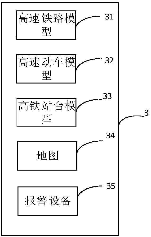
[0039] figure 1 It is a schematic diagram of a high-speed rail earthquake monitoring, early warning and emergency response demonstration system, the system includes: a wave output device 1, a vibration device 2, a high-speed rail sand table platform 3, an acceleration sensor 4, and a high-speed rail earthquake monitoring cabinet 5; wherein:
[0040] The wave output device 1 is connected to the vibration device 2 , and the wave output device 1 stores historical seismic waveforms in advance, and outputs at least one of the historical seismic waveforms to the vibration device 2 . The wave output device 1 stores a large number of historical and real seismic waveforms, and can truly simulate the occurrence of an earthquake when no earthquake occurs outdoors.
[0041] The vibrating device 2 is connected to the high-speed rail sand table platform 3, and the vibrating device 2 generates vibrations according to the historical earthquake waveform, driving the high-speed rail sand table ...
Embodiment 2
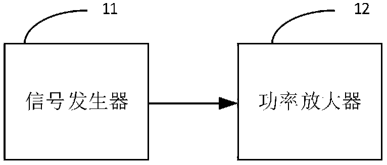
[0050] figure 2 It is the system structural diagram of embodiment two, and the system includes: wave output device 1, vibration device 2, high-speed rail sand table platform 3, acceleration sensor 4, high-speed rail earthquake monitoring cabinet 5; Wherein, wave output device 1 includes: signal generator 11 , Power amplifier 12.
[0051] The output end of the wave output device 1 is connected with the vibration device 2, and the wave output device 1 generates a seismic waveform, and transmits the seismic waveform to the vibration device 2; actual deficiencies. In this embodiment, the wave output device 1 is composed of a signal generator and a power amplifier. The input end of the power amplifier is connected to the signal generator, and the output end is connected to the vibration device 2. The wave output device 1 generates seismic waveforms and drives the vibration device 2 The process is as follows: the signal generator 11 downloads and stores the required historical ea...
Embodiment 3
[0059] Figure 4 It is the system structure diagram of embodiment three, the system includes: wave output device 1, vibration device 2, high-speed rail sand table platform 3, acceleration sensor 4, high-speed rail earthquake monitoring cabinet 5; wherein, wave output device 1 includes: signal generator 11, power amplifier 12. The high-speed rail earthquake monitoring cabinet 5 includes: a power box 51 , a high-speed rail earthquake early warning unit 52 , a server 53 , a display 54 , and a control unit 55 .
[0060] The output end of the wave output device 1 is connected with the vibration device 2, and the wave output device 1 generates a seismic waveform, and transmits the seismic waveform to the vibration device 2; actual deficiencies. In this embodiment, the wave output device 1 is composed of a signal generator 11 and a power amplifier 12. The input end of the power amplifier 12 is connected with the signal generator, and the output end is connected with the vibration d...
PUM
 Abstract
Description
Claims
Application Information
 - R&D
- Intellectual Property
- Life Sciences
- Materials
- Tech Scout
- Unparalleled Data Quality
- Higher Quality Content
- 60% Fewer Hallucinations
Browse by: Latest US Patents, China's latest patents, Technical Efficacy Thesaurus, Application Domain, Technology Topic, Popular Technical Reports.
© 2025 PatSnap. All rights reserved.Legal|Privacy policy|Modern Slavery Act Transparency Statement|Sitemap|About US| Contact US: help@patsnap.com


