
Design scheme of three-phase to nine-phase step-up step-down auto-coupling phase-shifting transformer

A technology of phase-shifting transformers and autotransformers, which is applied in the direction of transformers, fixed transformers, and parts of transformers/inductors. It can solve problems such as bad, not strict symmetry, and weakening effects of low-order current harmonics, and achieve weakening effects. Good, good symmetry, less winding turns

Pending Publication Date: 2019-03-29
吉安伊戈尔电气有限公司 +2
View PDF1 Cites 2 Cited by
  • Summary
  • Abstract
  • Description
  • Claims
  • Application Information

AI Technical Summary

Problems solved by technology

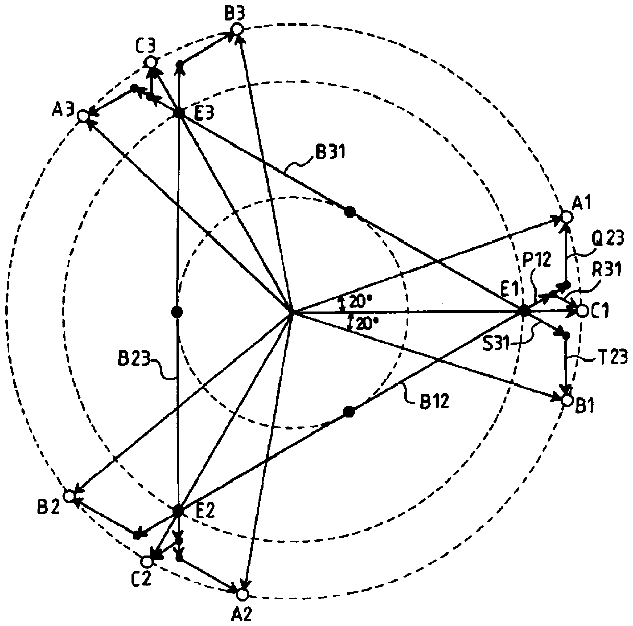
For example US Patent 2011 / 0051480A1, such as figure 1 As shown, although the three secondary windings are designed with a 20° electrical angle difference in turn, and each iron core column has six coils, but the phase part of the first autocoupling winding A (B, C) on the secondary side is connected to the third autocoupling The phase part of the coupling winding A (B, C) is not strictly symmetrical with respect to the axis of the second winding A (B, C) phase in practical applications, resulting in poor current low-order harmonic weakening effect on the primary winding side in practical applications.

Method used


Image

  • Design scheme of three-phase to nine-phase step-up step-down auto-coupling phase-shifting transformer
  • Design scheme of three-phase to nine-phase step-up step-down auto-coupling phase-shifting transformer
  • Design scheme of three-phase to nine-phase step-up step-down auto-coupling phase-shifting transformer

Examples


Embodiment Construction

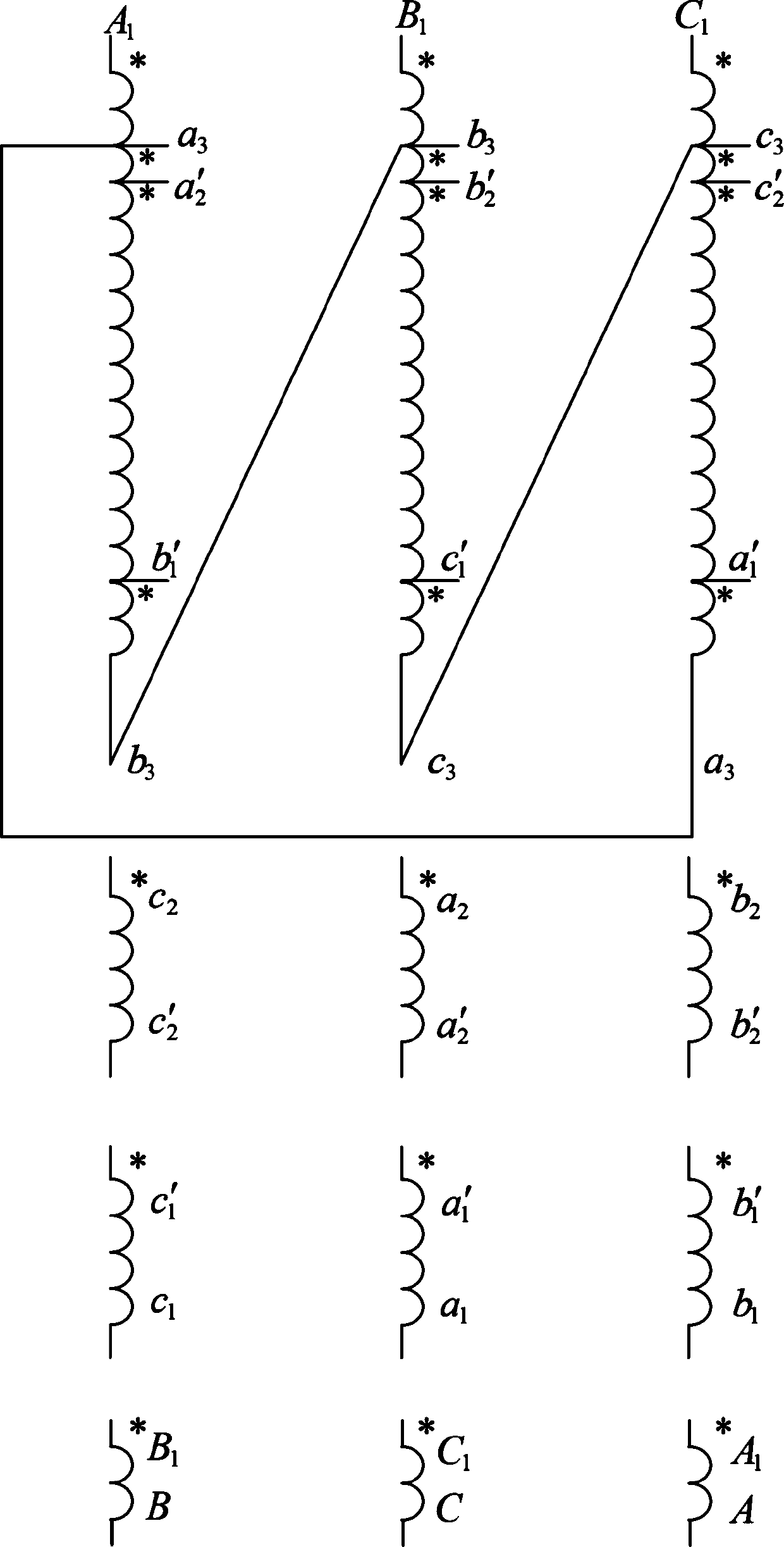
[0019] The structure, voltage phase vector diagram, etc. of the three-phase to nine-phase step-down or step-up auto-phase-shifting transformer product using the technical solution of the present invention will be described in detail below in conjunction with the accompanying drawings.

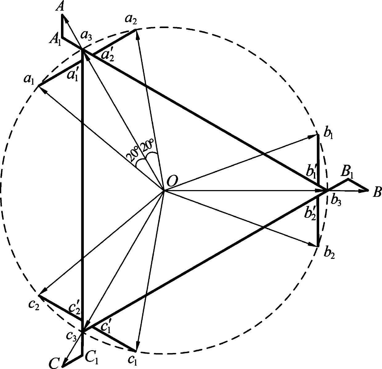
[0020] The first one is a three-phase to nine-phase step-down autophase-shifting transformer: the voltage phasor diagram is as follows figure 2 as shown, figure 2 The thick solid line in represents the turn distribution and connection, figure 2 The thin solid line in represents the voltage phasor.

[0021] 0A Indicates the phase A phase voltage of the primary side winding, Oa 1 , Oa 2 , Oa 3 Represents the three windings on the secondary side a 1 Mutually, a 2 Mutually, a 3 phase-to-phase voltage. OA and Oa 3 same phase, Oa 1 advanced Oa 3 20°, Oa 2 lag Oa 3 20°, Oa 1 and Oa 2 Corresponding coils about 0A perfectly symmetrical, 0a 3 and 0A Overlap...


PUM


Abstract

The invention provides a design scheme of a three-phase to nine-phase step-up step-down auto-coupling phase-shifting transformer. Secondary side windings are successively displaced by an electrical angle of 20 degrees. The secondary side 20-degree winding and a 20-degree winding are symmetric about its 20-degree winding axis, so a 20-degree voltage vector and a 20-degree voltage vector are symmetric about a voltage vector. The scheme has less additional winding turns of the three windings on the secondary side (20 degrees, 0, 20 degrees), good symmetry, and a resultant magnetic potential closer to a sine wave. A primary winding side has a good current low-order harmonic attenuation effect. The phase-shifting transformer with the auto-coupling structure has a design capacity only about 10%of a phase-shifting transformer of isolation structure, which can greatly reduce manufacturing cost.

Description

technical field [0001] The invention relates to an AC-to-DC power converter, in particular to a three-phase to nine-phase step-up and step-down self-coupling phase-shifting transformer in the AC-to-DC power converter. Background technique [0002] With the improvement of rectification power level, multi-pulse rectification circuits have been widely used in power electronics, motor drives, aircraft conversion systems, high-voltage direct current transmission and other fields. Although high-frequency PWM rectification can make the input current close to a sine wave, the cost is high, the switching loss is large, and the efficiency is not high, which limits the application of PWM rectification in high-power occasions. The multi-pulse rectification technology represented by the phase-shifting transformer plus uncontrolled rectification technology can effectively reduce the harmonic current on the input side, and has the advantages of high efficiency and strong overload capacity,...

Claims


Application Information

Patent Timeline
IPC IPC(8): H01F30/02H01F30/14H01F27/28H01F27/30
CPCH01F27/28H01F27/306H01F30/02H01F30/14
Inventor 陈乔夫张今朝李敬民肖俊承
Owner 吉安伊戈尔电气有限公司
Learn More