Electromagnetic vibration weakening method for permanent magnet driving motor of electric automobile

A technology of permanent magnet drive and electric vehicles, applied in electric vehicles, motors, electric components, etc., can solve the problems of increasing the manufacturing cost of motors, the difficulty of realizing motors, and the decrease of power density, etc., and achieves low processing costs, simple processing technology, and reduced The effect of small electromagnetic vibrations

Active Publication Date: 2020-05-22
SHANDONG UNIV
View PDF2 Cites 0 Cited by
  • Summary
  • Abstract
  • Description
  • Claims
  • Application Information

AI Technical Summary

Problems solved by technology

The existence of cogging torque will increase the torque ripple of the permanent magnet motor, which is not conducive to the application of the motor in high-precision control occasions
[0005] At present, the industry mainly uses the method of stator chute or rotor oblique pole to weaken the cogging torque and tooth harmonic electromotive force of the permanent magnet motor, so as to achieve the purpose of weakening the torque ripple, but the method of oblique pole or chute reduces the motor torque. The efficiency of manufacturing increases the cost of motor manufacturing, resulting in a decrease in power density or an increase in the amount of permanent magnets, which brings additional axial force and increases and reduces the electromagnetic vibration caused by the axial force of the motor; at the same time, the axial length of the motor is longer Difficult to achieve in a short time

Method used


Image

  • Electromagnetic vibration weakening method for permanent magnet driving motor of electric automobile
  • Electromagnetic vibration weakening method for permanent magnet driving motor of electric automobile
  • Electromagnetic vibration weakening method for permanent magnet driving motor of electric automobile

Examples


Embodiment 1

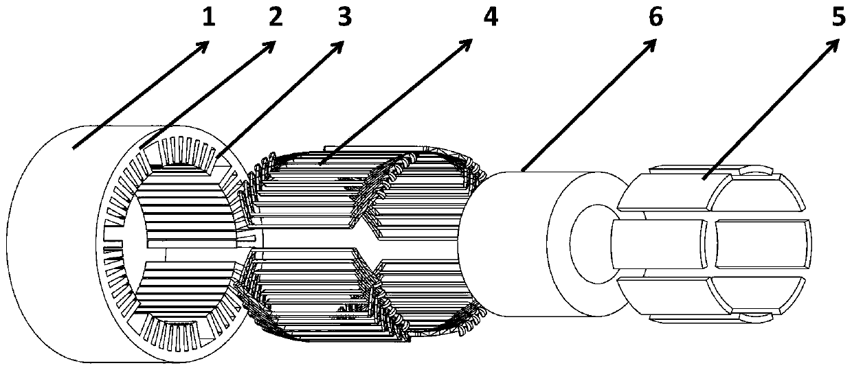
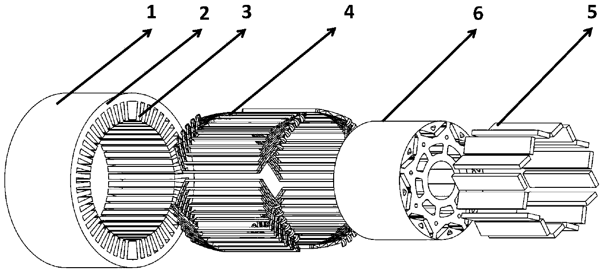
[0050] This embodiment relates to a method for weakening electromagnetic vibration of a permanent magnet drive motor of an electric vehicle, in particular to a method for weakening electromagnetic vibration of a permanent magnet synchronous motor combined with unequal slot widths. The motor includes a stator, a permanent magnet rotor, and an armature winding. The structure of the stator is different from that of conventional permanent magnet synchronous motor stators. The new stator has a combined structure with unequal slot widths. The width of all the teeth on the stator is the same. The sum of the widths of all the slots of the stator is kept constant, and the total slot area of ​​all the slots of the stator is kept constant. By changing one of the slots of the stator or The width of multiple slots, making it different from other slot widths.

[0051] Through this combination of unequal slot widths, the cogging torque, tooth harmonic electromotive force and torque ripple o...


PUM


Abstract

The invention discloses an electromagnetic vibration weakening method for a permanent magnet driving motor of an electric automobile. The method comprises: stator grooves are disposed between stator teeth, and armature windings are disposed in the stator grooves; the width of at least one stator slot in the stator slots is different from the widths of other stator slots, and the widths of other stator slots are the same; the stator slots adopt straight slot structures, the ratio of the total slot width to the pitch of the motor is kept unchanged, and the total slot area of the motor is kept unchanged; the circumferential angles of the stator slots with different widths and the circumferential angles of the other stator slots with the same width are determined by Kt, and the value of Kt ischanged to enable Gn to be equal to 0; and Gn is the influence of the distribution of the stator slots on the cogging torque, and Kt is the ratio of the widths of other stator slots with the same width to the widths of stator slots with different widths. The torque ripple weakening effect equivalent to that of a stator skewed slot can be achieved by changing the width of a motor stator slot, and the torque ripple weakening effect can be achieved by replacing a stator skewed slot or rotor skewed pole method in the industry.

Description

technical field [0001] The present disclosure relates to the technical field of electromagnetic vibration weakening of a permanent magnet synchronous motor, in particular to a method for weakening electromagnetic vibration of a permanent magnet drive motor of an electric vehicle. Background technique [0002] The statements in this section merely provide background information related to the present disclosure and do not necessarily constitute prior art. [0003] In recent years, with the improvement of high temperature resistance and the reduction of price of permanent magnet materials, permanent magnet motors have been widely used in national defense, industry, agriculture and daily life. Compared with other motors, permanent magnet synchronous motors have simple structure, Higher output torque density and higher efficiency. The permanent magnet motor with superior performance can meet the high requirements of the servo system on the motor. The torque ripple of the motor ...

Claims


Application Information

Patent Timeline
Patent Type & Authority Applications(China)
IPC IPC(8): H02K1/16H02K21/14
CPCH02K1/165H02K21/14H02K2213/03Y02T10/64
Inventor 王道涵薛东辉
Owner SHANDONG UNIV
Why Eureka
Try Eureka