
A method for commutating phases of DC brushless motors

A brushless DC motor, abnormal state technology, applied in the direction of electronic commutator, motor control, electronic commutation motor control, etc. simple effect

Active Publication Date: 2022-04-01
NANJING UNIV OF SCI & TECH
View PDF8 Cites 0 Cited by
  • Summary
  • Abstract
  • Description
  • Claims
  • Application Information

AI Technical Summary

Problems solved by technology

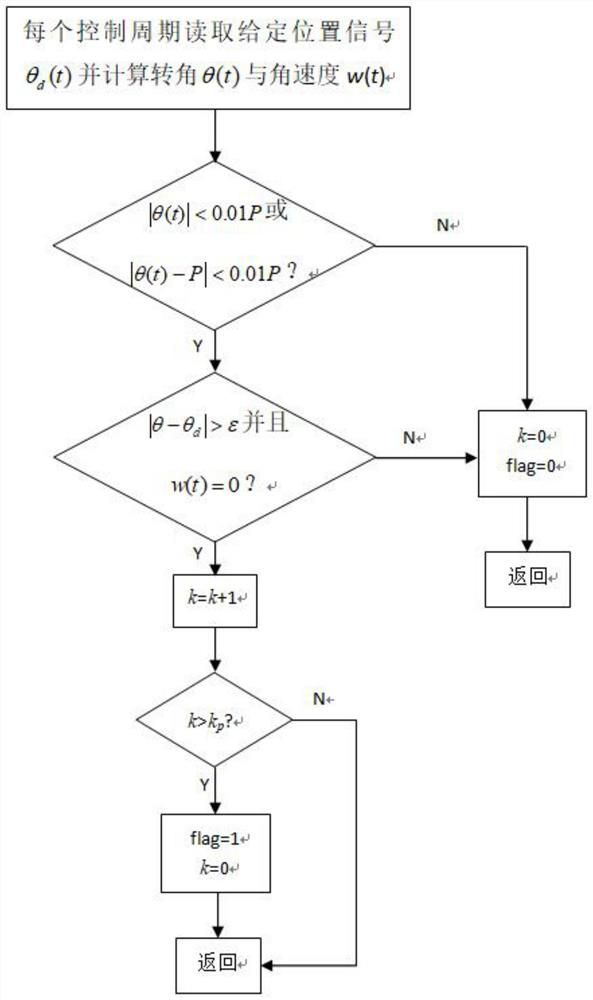
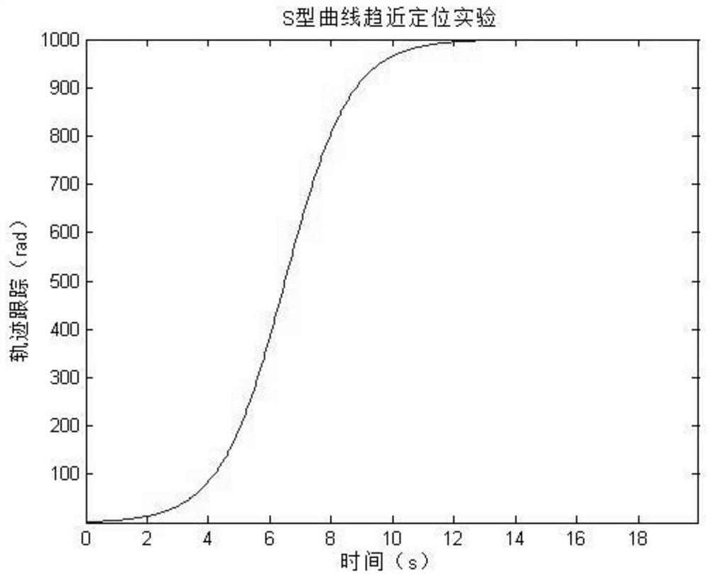
[0004] In order to solve the above problems, the present invention provides a brushless DC motor phase commutation method, which effectively solves the problem that the brushless DC motor approaches the target angle according to the S-shaped curve trajectory, and the motor cannot reach the required positioning due to stalling near the starting point and the end point. Accuracy problem, to realize the rapid self-start when the low-speed brushless DC motor is locked.

Method used


Image

  • A method for commutating phases of DC brushless motors
  • A method for commutating phases of DC brushless motors
  • A method for commutating phases of DC brushless motors

Examples


Embodiment Construction

[0035] In order to make the object, technical solution and advantages of the present invention clearer, the present invention will be further described in detail below in conjunction with the accompanying drawings and embodiments. It should be understood that the specific embodiments described here are only used to explain the present invention, not to limit the present invention.

[0036] The implementation of the present invention will be described in detail below in conjunction with specific embodiments.

[0037] In the drawings of this embodiment, the same or similar symbols correspond to the same or similar components; The indicated orientation or positional relationship is based on the orientation or positional relationship shown in the drawings, and is only for the convenience of describing the present invention and simplifying the description, rather than indicating or implying that the referred device or element must have a specific orientation, or in a specific orien...


PUM


Abstract

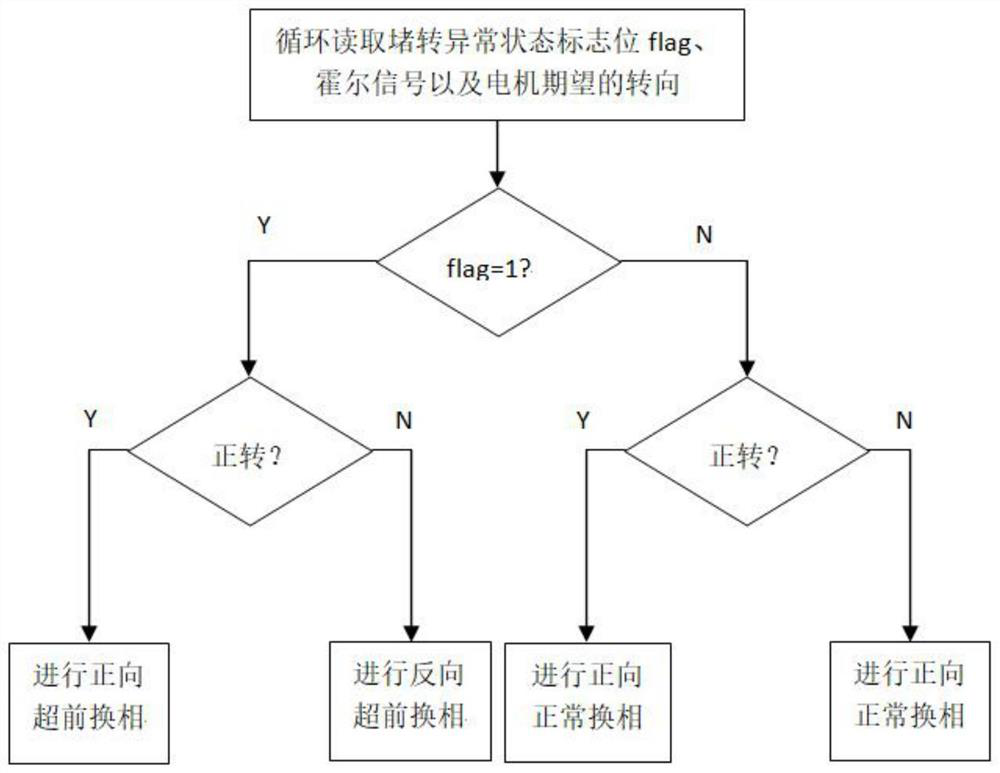
The invention discloses a phase commutation method of a DC brushless motor. A locked rotor detector is used to detect whether the DC brushless motor is locked near the starting point or the end point of the S-curve track and causes the motor to fail to meet the requirements. Positioning accuracy ε, and then control the commutation of the motor based on the output signal of the stall detector. When the motor is in a stalled state and cannot reach the required positioning accuracy, advanced commutation is implemented in the current control cycle, so that the stator Compared with the synthetic magnetic field generated by the normal commutation scheme, the synthetic magnetic field generated by the winding is 60° electrical angle ahead of the expected steering of the motor, attracting the rotor permanent magnet to rotate again; otherwise, normal commutation is implemented in the current control cycle. The invention effectively solves the problem that the DC brushless motor approaches the target angle according to the S-shaped curve track, and the motor cannot meet the required positioning accuracy due to stalling near the start point and the end point.

Description

technical field [0001] The invention relates to the field of motor control, in particular to a phase commutation method of a DC brushless motor. Background technique [0002] Brushless DC motors not only have the advantages of traditional DC motors, such as good mechanical characteristics and speed regulation characteristics, large starting torque, strong overload capacity, convenient adjustment, good dynamic characteristics, etc., but also have the advantages of simple structure of AC motors, reliable operation, It has a series of features such as easy maintenance, so it has been widely used in many high-tech fields, such as laser processing, robots and CNC machine tools. [0003] Current research on BLDC motors rarely addresses the low-speed performance of BLDC motors. When the brushless DC motor is running at high speed, it is easy to turn over the commutation point under the action of the moment of inertia (ie inertial force) and electromagnetic torque, so that the comm...

Claims


Application Information

Patent Timeline
Patent Type & Authority Patents(China)
IPC IPC(8): H02P6/14H02P6/15
CPCH02P6/14H02P6/153H02P2207/05
Inventor 张登峰庄浩陆宝春李军
Owner NANJING UNIV OF SCI & TECH
Learn More