Eureka AIR delivers breakthrough ideas for toughest innovation challenges, trusted by R&D personnel around the world.

Adaptive pulse width detection method of OTDR module for optical cable monitoring

An adaptive, pulse width technology, applied in the field of optical communication, can solve problems such as smearing, large blind spots, and wrong analysis results

Active Publication Date: 2019-03-29
GUILIN G LINK TECH
View PDF6 Cites 0 Cited by
  • Summary
  • Abstract
  • Description
  • Claims
  • Application Information

AI Technical Summary

Problems solved by technology

[0003] However, the actual situation is that when the optical fiber to be tested is broken, its length changes, and the original test pulse width may no longer be suitable for the current broken line.
In particular, when the optical fiber over 100km is broken into several hundred meters of optical fiber, and the test pulse width originally used for testing over 100km is used to test hundreds of meters of optical fiber, the dead zone may be too large, and the tailing may be serious and unavoidable. to the exact location of the fiber break, resulting in inaccurate alarm locations
[0004] In view of the above situation, it is necessary to enable the secondary test. The usual practice is to configure a typical test pulse width for different lengths of optical fibers. This approach is not a big problem for ideal optical fibers. The optical fiber is generally seriously degraded, and the test pulse width that does not consider the actual loss of the optical fiber may not be dynamic enough, resulting in wrong analysis results

Method used


Image

  • Adaptive pulse width detection method of OTDR module for optical cable monitoring

Examples


Embodiment

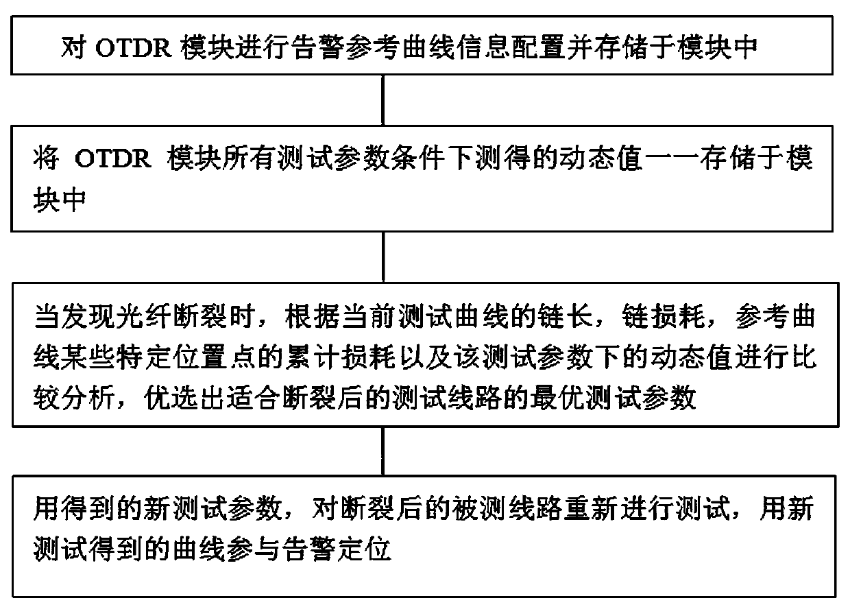
[0018] refer to figure 1 , a method for OTDR module self-adaptive pulse width detection in optical cable monitoring, comprising the steps:

[0019] 1) Configure the alarm reference test line information for the OTDR module and store it in the OTDR module;

[0020] 2) Store the corresponding dynamic values ​​measured in advance under all test parameters of the OTDR module in the OTDR module;

[0021] 3) When the fiber is found to be broken, the optical power alarm triggers the OTDR to use the original test parameters to initiate the first test of the fiber to be tested. When the actual chain length can be obtained, if the actual chain length is less than the chain length of the reference test line, the fiber is broken. , if the blind area of ​​the original test parameters is too large and the actual chain length cannot be obtained, check the loss value at the end of the fiber to be tested. If it is lower than the noise level, the fiber is broken. According to the chain length ...


PUM


Abstract

The invention discloses an adaptive pulse width detection method of an OTDR module for optical cable monitoring. The adaptive pulse width detection method comprises the steps of: (1), performing alarmreference test circuit information configuration on the OTDR module; (2), storing corresponding dynamic values obtained by measurement in advance under all test parameter conditions of the OTDR module in the OTDR module in one-to-one correspondence; (3), according to the chain length and the chain loss of a current test circuit, the cumulative loss of a specific position point of a reference testcircuit and the dynamic state under a test parameter, performing comparative analysis, and preferably selecting the test pulse width suitable for a broken test circuit; and (4), testing the broken test circuit again by using the test pulse width parameters of the test circuit obtained in the step (3), so that an alarm positioning position is obtained according to a test circuit result obtained bya new test. By means of the method, a too-large blind area and a trailing problem due to the fact that the original test pulse width is used after an optical fibre to be tested is broken can be avoided; and the alarm positioning accuracy can be improved.

Description

technical field [0001] The invention relates to optical communication technology, in particular to optical cable monitoring, in particular to a method for adaptive pulse width detection of an OTDR module in optical cable monitoring. Background technique [0002] In a traditional optical cable monitoring system, when an optical power alarm occurs, the control unit in the optical cable monitoring system will drive the OTDR module to test the test parameters of the optical fiber to be tested using the reference curve, and then compare and analyze the test curve with the reference curve, thereby Get the location of the alarm. [0003] However, the actual situation is that when the optical fiber to be tested is broken, its length changes, and the original test pulse width may no longer be suitable for the current broken line. In particular, when the optical fiber over 100km is broken into several hundred meters of optical fiber, and the test pulse width originally used for testi...

Claims


Application Information

Patent Timeline
Patent Type & Authority Applications(China)
IPC IPC(8): H04B10/079
CPCH04B10/079H04B10/0791H04B10/0795H04B10/07955
Inventor 王强文金朝周晓伟黄凤玲
Owner GUILIN G LINK TECH
Why Eureka
Eureka Blog
Learn More