Integrated device mounted based on monitoring device

A technology for monitoring equipment and cabinets, which is applied to the legs of general furniture, the combination of two or more pieces of different types of furniture, and extendable tables. problem, to achieve the effect of easy portability and reduced size

Inactive Publication Date: 2019-04-02
TIANJIN CHUANGTONG TECH
View PDF0 Cites 1 Cited by
  • Summary
  • Abstract
  • Description
  • Claims
  • Application Information

AI Technical Summary

Problems solved by technology

Due to the location uncertainty, mobility, and sudden nature of on-site work, technical experts often cannot rush to the site in the first time. Once problems and difficulties are encountered in the on-site operation, they can only communicate by phone, and the site and the command center cannot communicate with each other. Real-time collaborative office cannot achieve the purpose of on-site mobile office, which will result in low efficiency of construction work. In order to solve this problem, the designer has developed an integrated device
[0003] Since the integrated device is to help the on-site staff and the command center to work together, the integrated device includes a computer turntable and an operating platform for the staff. In order to meet this feature, the existing integrated device is bulky and cannot Folding, it is difficult for the staff to move, and the tools used for maintenance and construction are directly stacked in the tool box, which is inconvenient for the staff to find when using

Method used


Image

  • Integrated device mounted based on monitoring device
  • Integrated device mounted based on monitoring device
  • Integrated device mounted based on monitoring device

Examples


Embodiment approach

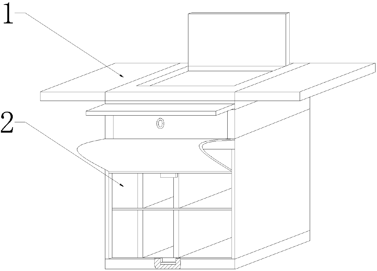
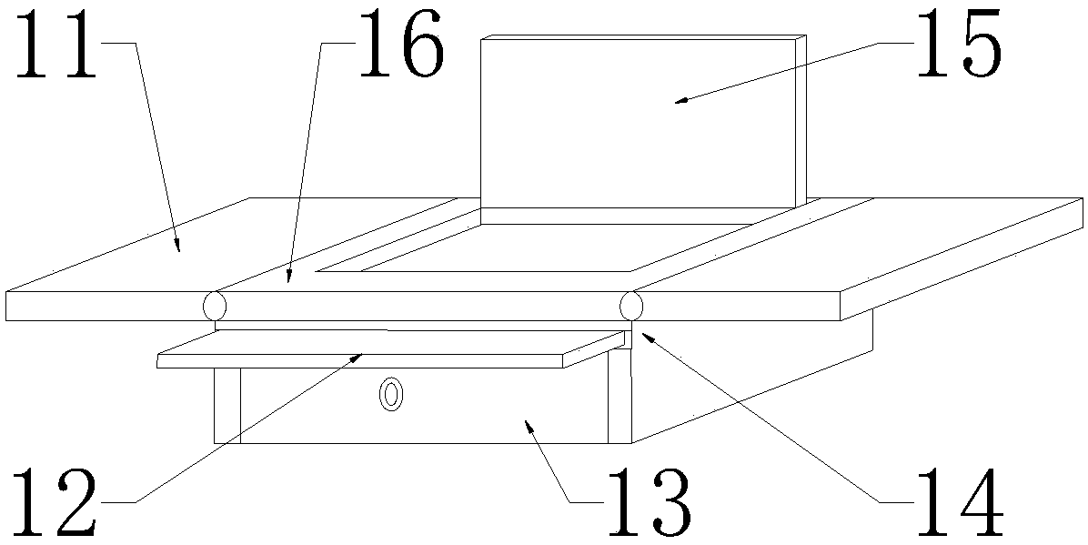
[0026] Specific embodiments: when the present invention is not needed, the staff takes out the computer from the computer placement slot at the top of the main table board 16, and then rotates the rotating backing plate 15 downward until the lower end of the turning backing board 15 fits with the upper end of the computer placement slot , and then the staff rotates the folding plate 11 to realize that the upper end of the folding plate 11 fits with the upper end of the main table plate 16, and then the staff holds the auxiliary handle at the front end of the extension plate 12 and pushes the extension plate 12 backward to realize the folding plate 11. The folded storage of the backing plate 15 and the extended flat plate 12 reduces the volume of the working platform assembly 1 while ensuring the use space of the staff.

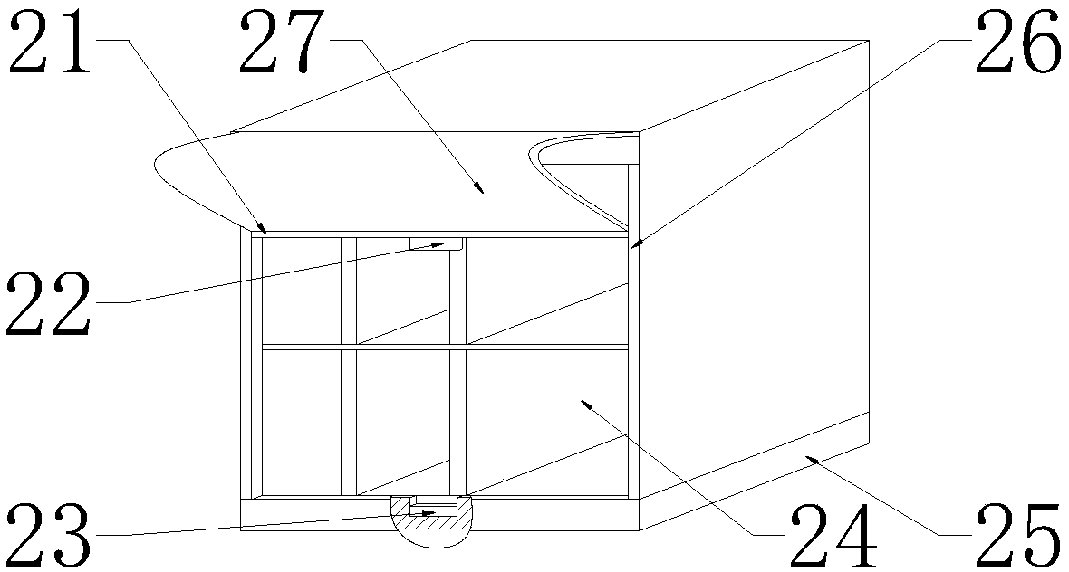
[0027] The staff classifies the tools for maintenance and construction into the separate storage box 24, then holds the auxiliary handle at the front end of th...


PUM


Abstract

The invention provides an integrated device mounted based on a monitoring device. The integrated device comprises an extension flat plate, a box, a rotating backup plate, a main table board, a slide bar, an iron block, an electromagnet, a partitioned storage box, a bottom plate, slideways and dust cloth, wherein the rotating backup plate is mounted at the upper end of the main table board, the boxis mounted at the lower end of the main table board, and the extension flat plate is embedded at the front end of the box. According to the design, folding can be realized, so that the carrying of aworker is facilitated, the slideways are symmetrically mounted at the front end of the partitioned storage box, the slideways are symmetrically mounted at the left and right ends of the slide bar, thedust cloth is mounted at the upper end of the slide bar, the dust cloth is mounted at the upper part of the front end of the partitioned storage box, the bottom plate is arranged at the lower end ofthe partitioned storage box, the electromagnet is mounted at the upper end of the bottom plate, the iron block is arranged at the upper side of the electromagnet, and the iron block is fixed at the lower end of the slide bar. Due to the adoption of the design, the worker can conveniently find tools, the device is convenient to use and small in size, the work efficiency of the worker is improved, and the reliability is high.

Description

technical field [0001] The invention is an integrated device based on the installation of monitoring equipment, which belongs to the field of monitoring equipment. Background technique [0002] In recent years, there is a common problem in field operations and on-site repairs of power systems in my country, that is, the disconnection between field work and the background command center. Due to the location uncertainty, mobility, and sudden nature of on-site work, technical experts often cannot rush to the site in the first time. Once problems and difficulties are encountered in the on-site operation, they can only communicate by phone, and the site and the command center cannot communicate with each other. Real-time collaborative office cannot achieve the purpose of on-site mobile office, which will result in low efficiency of construction work. In order to solve this problem, the designer has developed an integrated device. [0003] Since the integrated device is to help t...

Claims


Application Information

Patent Timeline
Patent Type & Authority Applications(China)
IPC IPC(8): A47B37/00A47B1/05A47B13/08A47B21/04A47B83/04A47B96/20
CPCA47B1/05A47B13/081A47B21/04A47B37/00A47B83/045A47B96/202
Inventor 朱勇
Owner TIANJIN CHUANGTONG TECH
Why Eureka
Try Eureka