Spring chamfering machine

A chamfering machine and chamfering technology, which is applied in the direction of grinding frames, parts of grinding machine tools, machine tools suitable for grinding workpiece edges, etc. Low efficiency and other problems, to avoid the time-consuming cleaning, convenient replacement and maintenance, and shorten the time-consuming effect

Active Publication Date: 2019-04-02
肇庆市肇大体育科技有限公司
View PDF8 Cites 4 Cited by
  • Summary
  • Abstract
  • Description
  • Claims
  • Application Information

AI Technical Summary

Problems solved by technology

[0003] In order to make up for the deficiencies in the prior art, the present invention proposes a spring chamfering machine, which is mainly used to solve the problem that the existing spring chamfering machine cannot fix the spring well, resulting in low spring chamfering efficiency and poor chamfering effect. bad question

Method used


Image

  • Spring chamfering machine
  • Spring chamfering machine
  • Spring chamfering machine

Examples


Embodiment Construction

[0024] In order to make the technical means, creative features, goals and effects achieved by the present invention easy to understand, the present invention will be further described below in conjunction with specific embodiments.

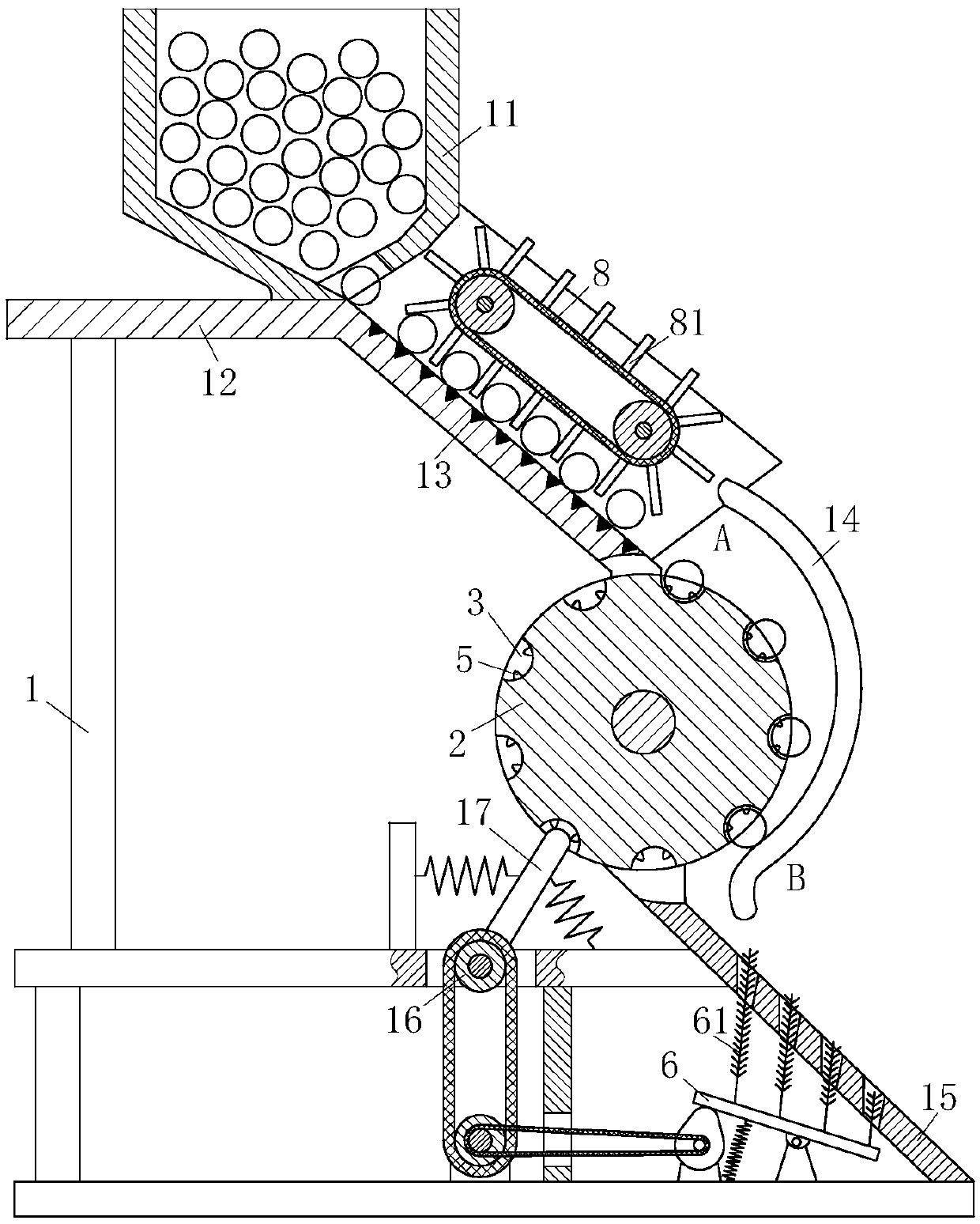
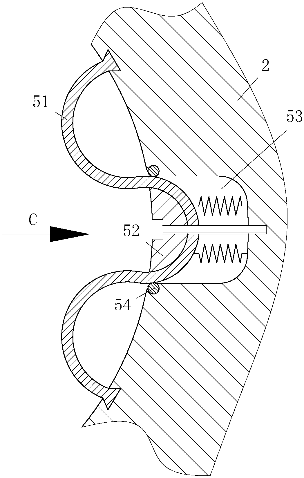
[0025] like Figure 1 to Figure 6 As shown, a kind of spring chamfering machine of the present invention comprises a frame 1, the top of the frame 1 is fixed with a feed hopper 11 loaded with springs, the lower right corner of the feed hopper 11 is provided with an outlet, and the top of the frame 1 A material guide plate 12 connected to the feed hopper 11 is provided, the right side of the material guide plate 12 is bent into a slope, and a plurality of magnetic strips 13 are evenly arranged on the slope of the material guide plate 12; There is a clamping roller 2 driven by a motor, and the clamping roller 2 is evenly provided with a plurality of placement grooves 3 in the upper direction, and the placement grooves 3 are used to place springs; th...


PUM


Abstract

The invention belongs to the technical field of spring machining equipment, and particularly relates to a spring chamfering machine. The machine comprise a machine frame, wherein a feeding hopper is fixed at the top of the machine frame, a material guide plate connected with the feeding hopper is arranged at the top of the machine frame, the right side of the material guide plate is bent to a slope, and a plurality of magnetic strips are uniformly arranged on the slope of the material guide plate; a clamping roller driven by a first motor is arranged in the machine frame, and a plurality of placing grooves are uniformly formed in the clamping roller in the circumferential direction; an arc-shaped pressing plate is arranged at the lower end of the material guide plate, the pressure plate isarranged on the front-rear face board of the material guide plate, the gap between the pressing plate and the clamping roller is gradually reduced from the position A to the position B, and when a spring moves to the position B, the spring is just clamped through the pressing plate and the clamping roller; two cylindrical chamfering blocks driven by a second motor are arranged in the machine frame, a chamfer is arranged at the front end of each chamfering block, the two chamfering blocks are front-back symmetrically distributed on the two sides of the clamping roller correspondingly, and therotating directions of the two chamfering blocks are opposite; and a discharging plate is arranged at the position, located below the clamping roller, of the machine frame, and four through grooves are uniformly formed in the discharging plate.

Description

technical field [0001] The invention belongs to the technical field of spring processing equipment, in particular to a spring chamfering machine. Background technique [0002] At present, the spring industry is developing rapidly, and most springs require external chamfering. The chamfering of the outer edges of both ends of the spring is to make it easy to insert the spring when it fits into the hole, and on the other hand, it is not to hurt the operator's hands, because the outer edges of the spring without chamfering generally have burrs, etc. , you will stab your hand if you are not careful. Chamfering the outer edges of the two ends of the spring can also avoid the phenomenon of spring stress concentration. The spring chamfering machine is a machine used to chamfer the outer edges of the two ends of the spring, but the existing spring chamfering machines are not highly automated and not smart enough, and the existing spring chamfering machines cannot make the spring b...

Claims


Application Information

Patent Timeline
Patent Type & Authority Applications(China)
IPC IPC(8): B24B9/04B24B41/00B24B41/06B24B47/12B24B41/02B08B1/02
Inventor 李艳梅许伟喜陈英俊陈庆华陈小童
Owner 肇庆市肇大体育科技有限公司
Why Eureka
Try Eureka