Generator end cover clamping device

A generator end and cover clamp technology, applied in workpiece clamping devices, manufacturing tools, etc., can solve the problems of fixed operation, complexity, etc.

Active Publication Date: 2019-04-02
CHONGQING YIZHICHI MACHINERY
View PDF7 Cites 3 Cited by
  • Summary
  • Abstract
  • Description
  • Claims
  • Application Information

AI Technical Summary

Problems solved by technology

[0003] The purpose of the present invention is to provide a generator cover clamping device to solve the problem of complex operation of the fixing method

Method used


Image

  • Generator end cover clamping device
  • Generator end cover clamping device
  • Generator end cover clamping device

Examples


Embodiment Construction

[0023] The following is further described in detail through specific implementation methods:

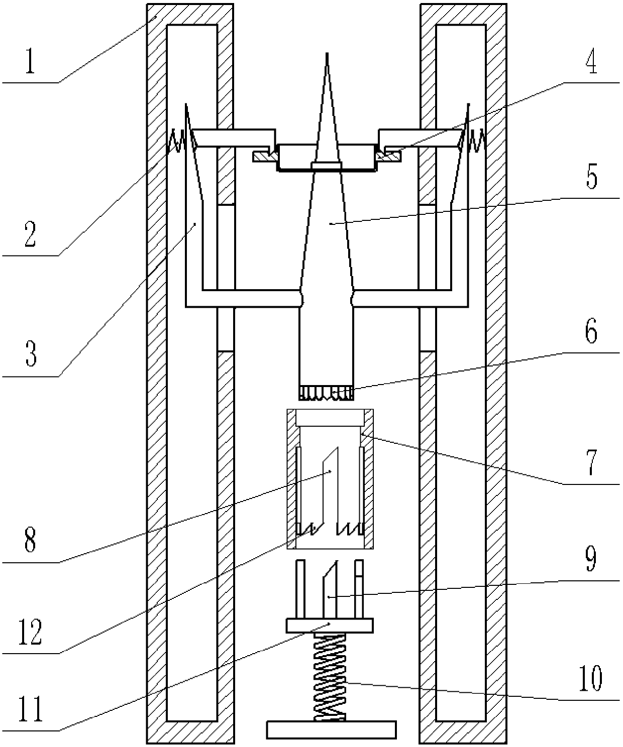
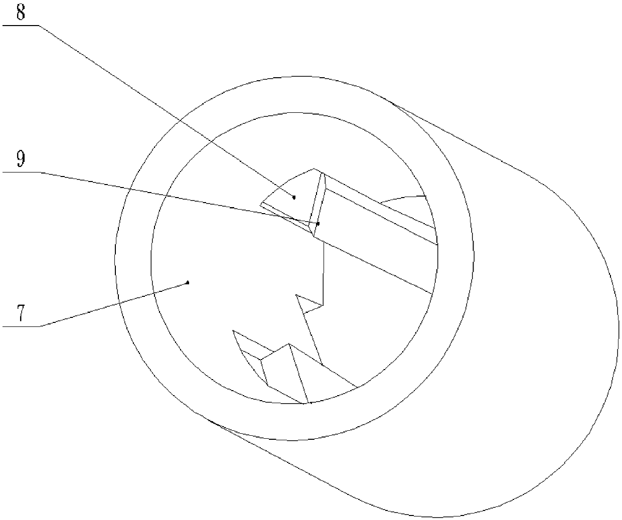
[0024] The reference signs in the drawings of the specification include: limit plate 1, second spring 2, limit rod 3, generator end cover 4, support column 5, push claw 6, support cylinder 7, slideway 8, slide claw 9 , The first spring 10, the support plate 11, the wedge 12.

[0025] The generator cover clamping device includes a base, a support mechanism, a reset mechanism and a limit mechanism.

[0026] as combined figure 1 , figure 2 and image 3 As shown, the base includes a base, and a support cylinder 7 is fixedly connected above the base. The support cylinder 7 is a cylinder, and the axis of the support cylinder 7 is perpendicular to the plane of the base. The inner wall of the support cylinder 7 is provided with slideways 8, the number of slideways 8 is four, the slideways 8 are evenly arrayed in the circumferential direction of the support cylinder 7, and the sliding di...


PUM


Abstract

The invention belongs to the technical field of workpiece clamping devices, and particularly discloses a generator end cover clamping device. The generator end cover clamping device comprises a base,a supporting mechanism, a rest mechanism and a limiting mechanism. The base comprises a pedestal, and the pedestal is provided with a supporting cylinder. The supporting mechanism includes a supporting disk, and the supporting disk is slidably connected with the inner cavity of the supporting cylinder. The reset mechanism comprises a supporting column, and the circumferential side wall of the supporting column extends outwards to form pushing pawls. The limiting mechanism includes a plurality of limiting plates, limiting blocks and limiting rods, wherein the limiting plates are uniformly arranged on the periphery of a cylinder in an array mode. One ends of the limiting rods are fixedly connected to the outer wall of the supporting column, and the other ends of the limiting rods are slidably connected to inner cavities of the limiting plates. The generator end cover clamping device solves the problem of complex fixation mode.

Description

technical field [0001] The invention belongs to the technical field of workpiece clamping devices, and specifically discloses a generator end cover clamping device. Background technique [0002] The existing generator end cover has two modes: manual trimming and equipment trimming. The manual operation is time-consuming and laborious, which is not suitable for mass production. However, the processing of the end cover by mechanical equipment needs to be clamped, so it is necessary to use As far as the fixture is concerned, since the generator end cover is of irregular shape and the amount of processing is relatively large, the existing fixture is to fix the generator end cover on the processing table through threaded connection. However, due to the large production volume of the generator end cover, the threaded connection method takes a lot of time, which greatly affects the production efficiency and also increases the cost of factory production. Contents of the invention ...

Claims


Application Information

Patent Timeline
Patent Type & Authority Applications(China)
IPC IPC(8): B25B11/00
CPCB25B11/00
Inventor 王志立
Owner CHONGQING YIZHICHI MACHINERY
Why Eureka
Try Eureka